
Sealed kneading machine

一种混合搅拌、搅拌机的技术,应用在混合机、具有旋转搅拌装置的混合机、溶解等方向,能够解决混合搅拌时间变长、分布性能低等问题

Active Publication Date: 2016-04-06
KOBE STEEL LTD
View PDF6 Cites 0 Cited by
  • Summary
  • Abstract
  • Description
  • Claims
  • Application Information

AI Technical Summary

Problems solved by technology

If the distribution performance of the material to be mixed is low, the mixing time of the material to be mixed (the time required to mix the material to be mixed to the desired mixing state) may become longer
Therefore, in the internal mixers of conventional techniques 1 and 2, there is room for improvement in terms of productivity.

Method used


Image

  • Sealed kneading machine
  • Sealed kneading machine
  • Sealed kneading machine

Examples


Embodiment Construction

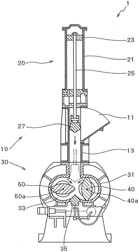
[0018] refer to Figure 1 to Figure 6 ,illustrate figure 1 The internal mixing mixer 1 shown.

[0019] The internal mixer 1 is a device for mixing and stirring the material to be mixed and stirred. The material to be mixed and stirred includes, for example, a polymer material. Examples of the polymer material include rubber and / or resin. The material to be kneaded is composed of, for example, rubber mixed with silica, a silane coupling agent, and the like. The internal mixer 1 is a batch mixer. The internal mixer 1 includes a supply unit 10 and a mixing unit 30 .

[0020] The supply unit 10 is a part that supplies the material to be kneaded to the kneading unit 30 . The supply unit 10 includes a hopper 11 , a material supply cylinder 13 , and a cylinder device 20 .

[0021] The material to be kneaded is thrown into the hopper 11 from the outside of the internal mixer 1 .

[0022] The material supply cylinder 13 is a cylinder through which the material to be kneaded ca...


PUM


Abstract

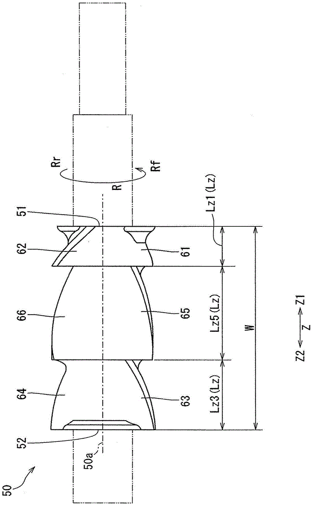
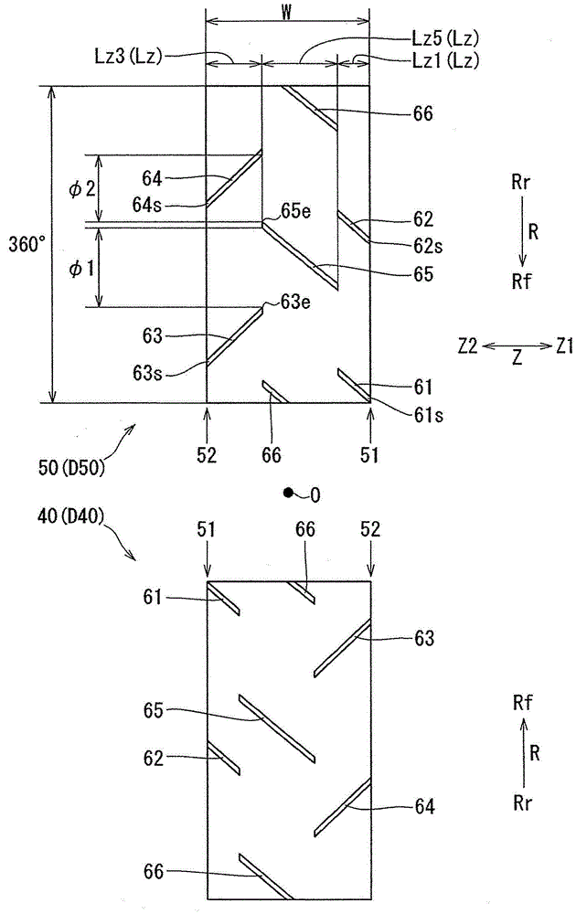
The sealed kneading machine of the present invention is provided with a kneading chamber to which a material to be kneaded is supplied, and a rotor disposed in the kneading chamber so as to be able to rotate about a rotor shaft. The rotor is provided with a plurality of kneading blades for kneading the material to be kneaded, and the length of all the kneading blades in the rotor shaft direction of each thereof is 45% or less of the total length of the rotor in the rotor shaft direction.

Description

technical field [0001] The present invention relates to an internal mixing mixer. Background technique [0002] Conventionally, there are internal mixers (see Patent Documents 1, 2, etc. below). The closed mixing mixer includes: a mixing chamber, which accepts the supply of materials to be mixed; and a rotor, which is arranged in the mixing chamber. The rotor includes a plurality of mixing blades for mixing the material to be mixed. Based on the rotation of the rotor, the mixing blade mixes the material to be mixed. [0003] Patent Document 1 as [Prior Art 1] (refer to the figure 2 and Figure 4 ) describes the following technology: the distribution and dispersibility of the materials to be mixed are taken into account by nonlinear blades (13). In paragraph [0017] of Patent Document 1, it is described as follows: when the total length of the rotor in the axial direction of the rotor is L, the length of the mixing blades (12, 13) in the axial direction of the rotor is se...

Claims


Application Information

Patent Timeline
Patent Type & Authority Applications(China)
IPC IPC(8): B29B7/18B01F7/08B29B7/20
CPCB29B7/183B29B7/186B29B7/246B29B7/263B29B7/7495
Inventor 龟田康弘山根泰明宫坂和夫福谷和久东孝祐
Owner KOBE STEEL LTD
Learn More