
Eureka
For R&D, Eureka makes reading and utilizing patents & technical documents easy.
Eureka AIR
Designed for self-driven R&D workflows. Generate viable solutions, solve complex R&D challenges, empower your innovation with AI.

Eureka Materials
Designed for material experts only. Revolutionize your material R&D, from search, analyze, to developing new materials.

TechResearch
Generate reliable direction feasibility study reports for your R&D in just a few steps.

TechSeek
Discover and master advanced knowledge NOW. Basics, ideas, possibilities, all at once.

TechMind
As an expert in R&D Theories, TechMind can generates customized viable solutions instantly.

TechRisk
Analyze your overall solution with one click, know your potential R&D risks in advance.

TechMonitor
Get weekly tech updates, stay abreast of the latest tech innovations and key insights.
Hydraulic machine loading system and control method thereof
A technology of loading system and control method, applied in the direction of presses, manufacturing tools, etc., can solve the problems of increased use and manufacturing costs, and achieve the effect of increasing the loading speed and speeding up the movement speed.
- Summary
- Abstract
- Description
- Claims
- Application Information
AI Technical Summary
Problems solved by technology
Method used
Image

Examples
Embodiment 1
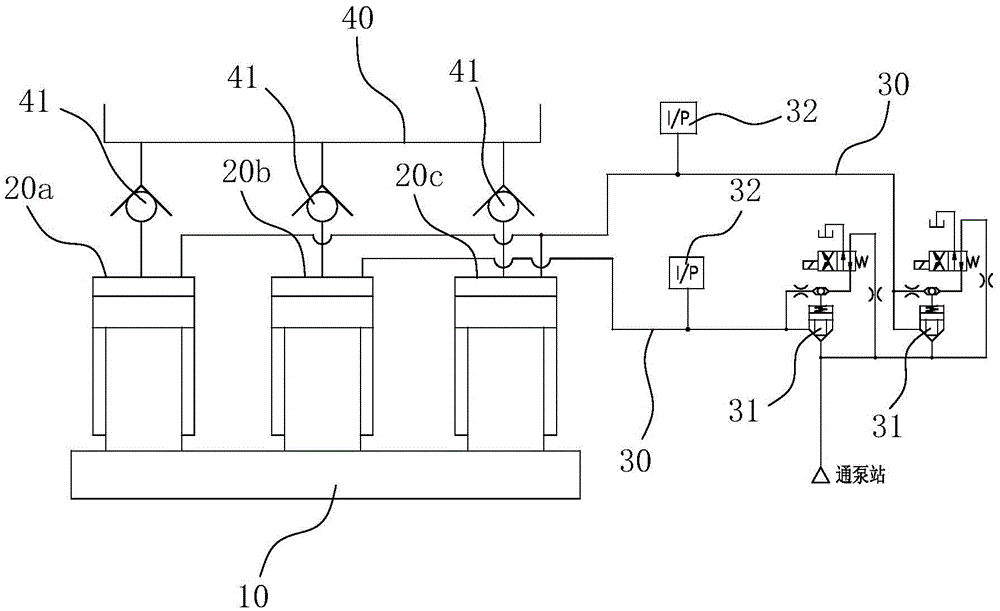
[0017] Such as figure 1 As shown, as a preferred embodiment of the present invention, there are three hydraulic cylinders, namely 20a, 20b, and 20c, and the three hydraulic cylinders 20a, 20b, and 20c are arranged in a line, wherein the upper chamber of the middle hydraulic cylinder 20b is connected with one road The loading oil passage 30 is connected, and the upper chambers of the two hydraulic cylinders 20a and 20c on the side are connected with another loading oil passage 30 .
[0018] When the slider just starts to enter the working stroke, due to the small load, the hydraulic oil provided by the pump station supplies oil to the middle hydraulic cylinder 20b through the control system, when the pressure sensor 32 of the middle hydraulic cylinder 20b detects that the pressure reaches the set pressure , the hydraulic oil provided by the pump station supplies oil to the hydraulic cylinders 20a and 20c on both sides through the control system. When the pressure sensors 32 of ...
Embodiment 2
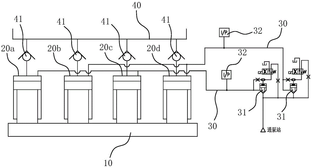
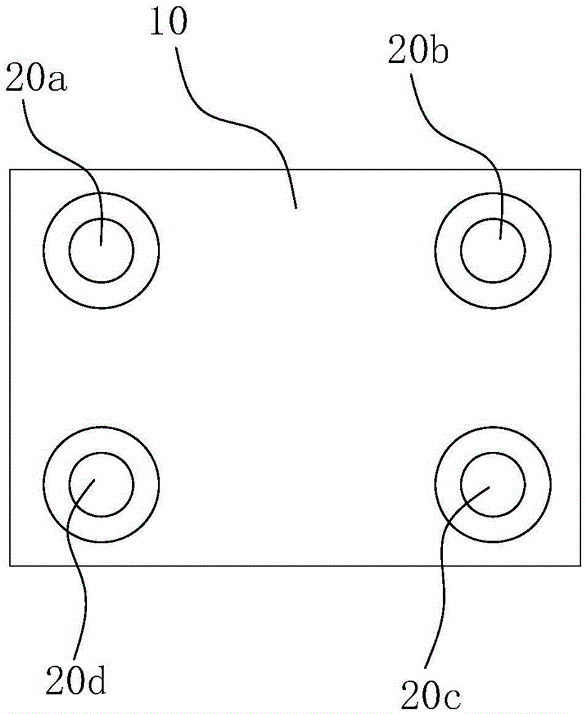
[0020] Such as figure 2 , 3 As shown, as another embodiment of the present invention, there are four hydraulic cylinders, namely 20a, 20b, 20c, and 20d, and the four hydraulic cylinders 20a, 20b, 20c, and 20d are arranged corresponding to the four corners of the hydraulic press slider. The two hydraulic cylinders 20a, 20c or 20b, 20d located on the same diagonal line communicate with the same loading oil passage 30 .
[0021] Both of the above two embodiments can ensure that any group of piston cylinders can uniformly apply pressure to the hydraulic press slider 10, thereby avoiding the tilting of the hydraulic press slider 10 due to uneven force during the staged loading process.
[0022] The present invention also provides a control method for the loading system of the hydraulic press, comprising the following steps:
[0023] a. Turn on the pump station;
[0024] b. Open one of the loading oil passages 30, while ensuring that the other loading oil passages 30 are closed;...
Embodiment approach
[0027] 1. If figure 1 As shown, when there are three hydraulic cylinders and the three hydraulic cylinders are lined up, the loading oil passage 30 of the middle hydraulic cylinder 20b is first opened, and when the loading oil passage 30 of the middle hydraulic cylinder 20b reaches a predetermined pressure, the loading oil passage 30 is closed. Then open the loading oil circuit 30 of the hydraulic cylinders 20a, 20c on both sides. When the loading oil circuit 30 of the hydraulic cylinders 20a, 20c on both sides reaches the predetermined pressure, open the loading of the three hydraulic cylinders 20a, 20b, 20c at the same time. oil circuit 30.
[0028] 2. If figure 2 , 3 As shown, when there are four hydraulic cylinders, and when the four hydraulic cylinders are respectively arranged corresponding to the four corners of the hydraulic machine slide block 10, first open the loading oil passages 30 of the two hydraulic cylinders 20a, 20c on the same diagonal line, when the Whe...
PUM
 Abstract
Description
Claims
Application Information
 - R&D Engineer
- R&D Manager
- IP Professional
- Industry Leading Data Capabilities
- Powerful AI technology
- Patent DNA Extraction
Browse by: Latest US Patents, China's latest patents, Technical Efficacy Thesaurus, Application Domain, Technology Topic, Popular Technical Reports.
© 2024 PatSnap. All rights reserved.Legal|Privacy policy|Modern Slavery Act Transparency Statement|Sitemap|About US| Contact US: help@patsnap.com