A parallel leg structure for high-speed running legged robot

A robot and foot technology, applied in the field of parallel leg structures of foot robots, can solve problems such as large energy consumption, and achieve the effects of large step length, small inertia and compact structure

Active Publication Date: 2018-01-30
SHENZHEN LONGHAITE ROBOT TECH CO LTD
View PDF7 Cites 0 Cited by
  • Summary
  • Abstract
  • Description
  • Claims
  • Application Information

AI Technical Summary

Problems solved by technology

[0004] The present invention solves the problem of large energy consumption caused by the periodic acceleration and deceleration of existing high-speed footed robots, and further provides a parallel leg structure for high-speed running footed robots

Method used


Image

  • A parallel leg structure for high-speed running legged robot
  • A parallel leg structure for high-speed running legged robot
  • A parallel leg structure for high-speed running legged robot

Examples


specific Embodiment approach 1

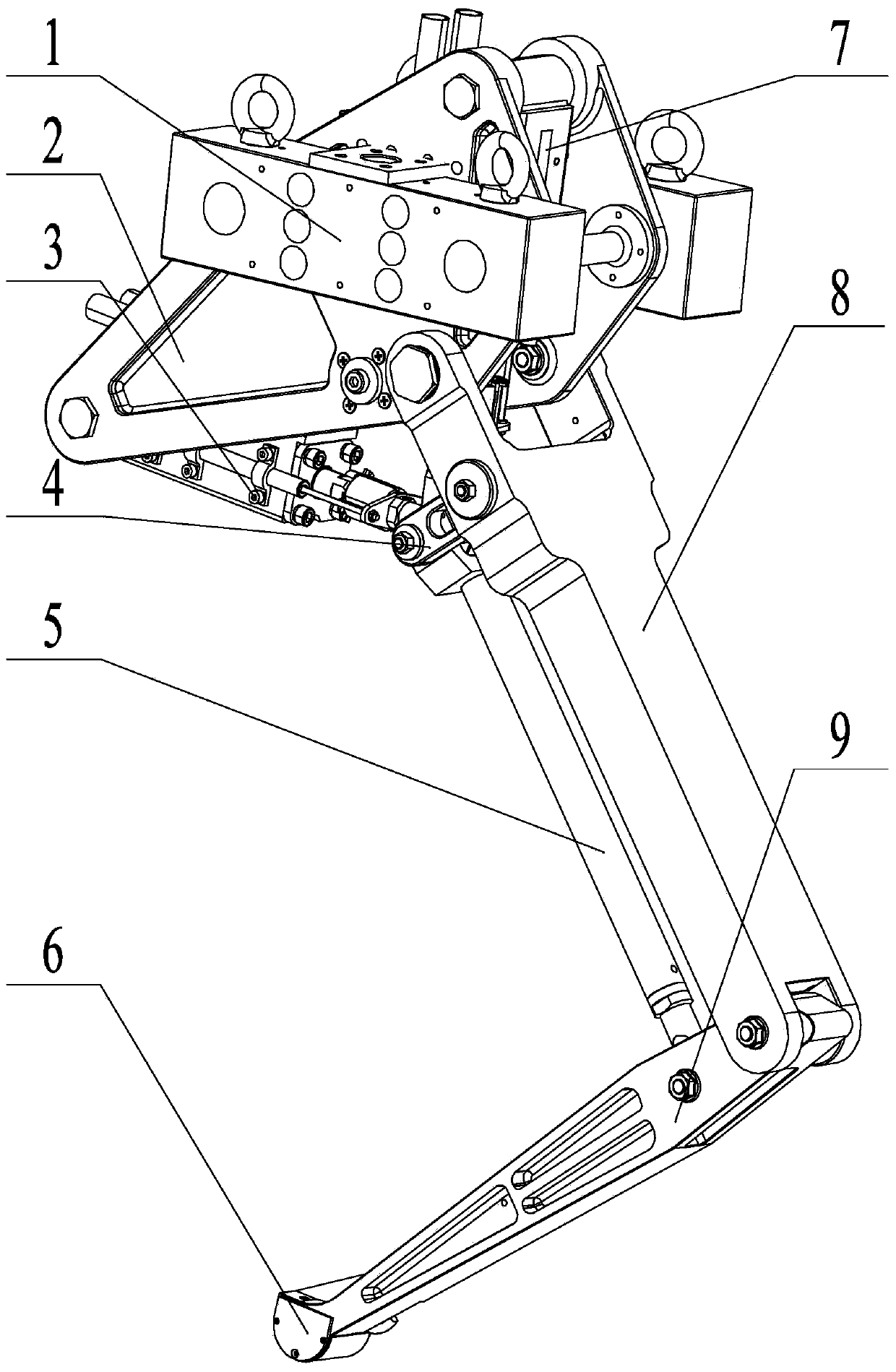
[0017] Specific implementation mode one: as Figure 1~6 As shown, the parallel leg structure for a high-speed running legged robot in this embodiment includes a shoulder blade 2, a horizontal hydraulic cylinder 3, a parallel short connecting rod 4, a parallel long connecting rod 5, a sole 6, a vertical hydraulic cylinder 7, and a thigh 8 , calf 9 and two joint legs load-bearing and lifting steel plate 1;

[0018] The scapula 2 is a frame body symmetrical on both sides, and the load-bearing and lifting steel plates 1 of the two joint legs are symmetrically fixed on the outer walls of both sides of the scapula 2 , the upper end of the thigh 8 is hinged to the lower part of the scapula 2 , and the lower end of the thigh 8 is connected to the lower part of the calf 9 . The upper end is hinged, the sole of the foot 6 is fixed on the lower end of the calf 9, the parallel short link 4 is hinged with the upper part of the thigh 8, the other end of the parallel short link 4 is hinged w...

specific Embodiment approach 2

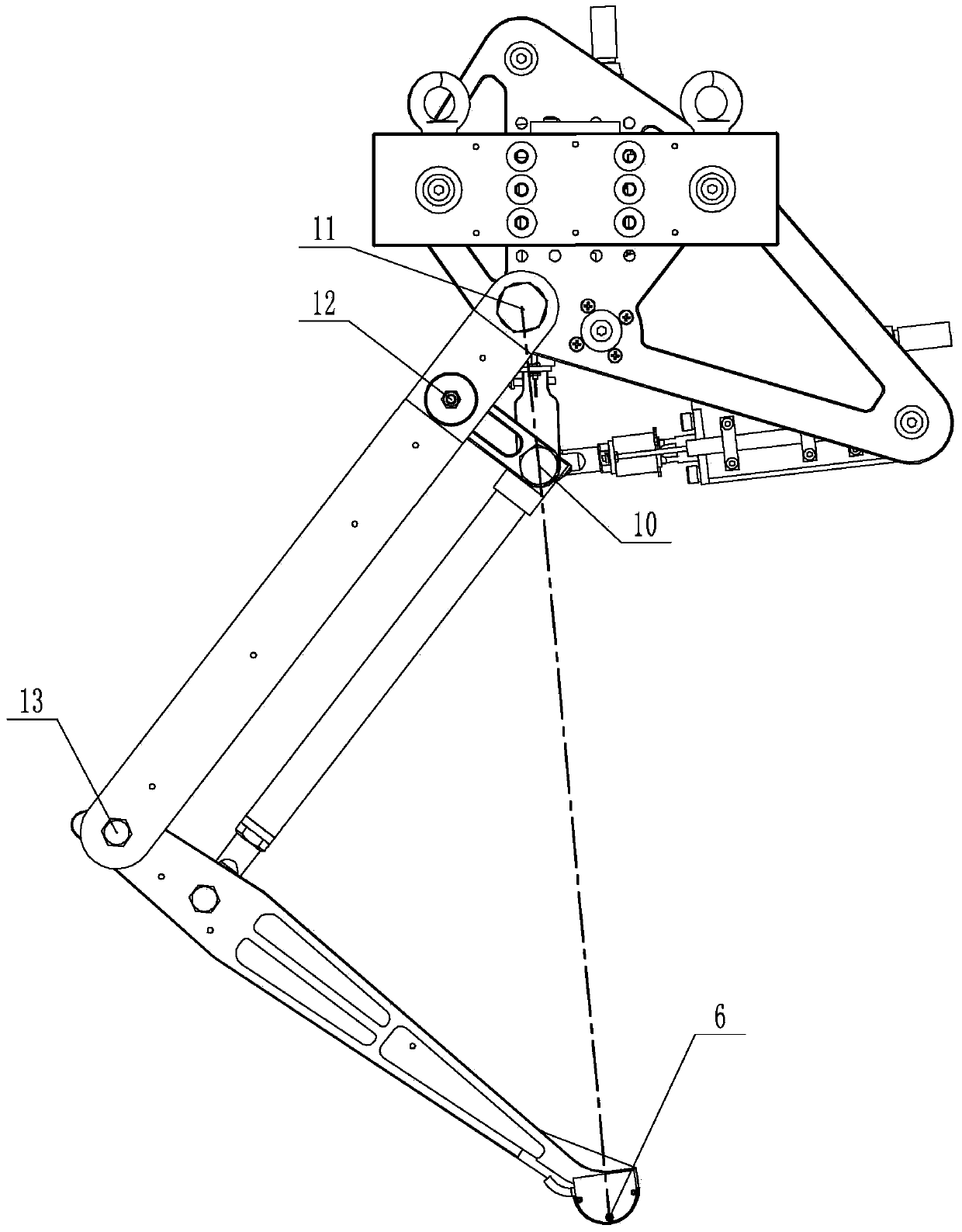
[0020] Specific implementation mode two: as figure 2 As shown, in this embodiment, the parallel short link 4 and the parallel long link 5 are connected through the first hinge point 10, the parallel short link 4 and the thigh 8 are connected through the second hinge point 12, and the thigh 8 and the calf 9 The thigh 8 and the scapula 2 are connected through the hip joint 11, the triangle formed by the first hinge point 10, the second hinge point 12 and the hip joint 11 is connected with the hip joint 11, the knee joint 13 and the sole 6 The formed triangle is a similar triangle; the parallel short connecting rod 4 is arranged parallel to the calf 9, the parallel long connecting rod 5 is arranged parallel to the thigh 8, and the three points of the hip joint 11, the first hinge point 10 and the center of the sole 6 are in a straight line superior. The structure of the above-mentioned magnifying ruler constitutes the profiling mechanism of the force, position and speed of the ...

specific Embodiment approach 3

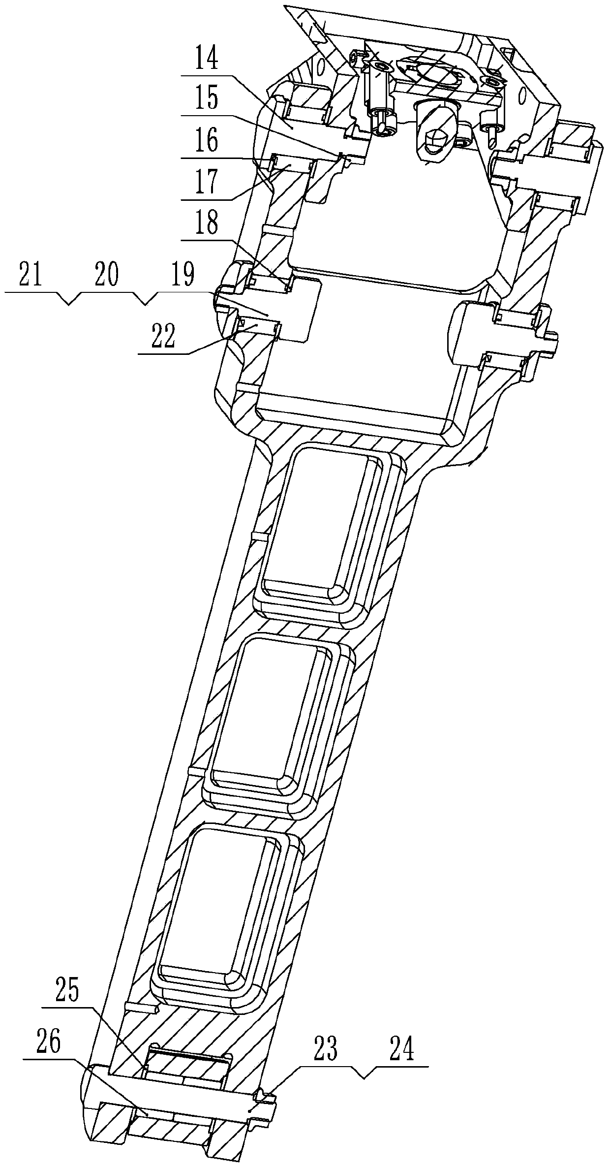
[0021] Specific implementation mode three: as image 3 As shown, the hip joint 11 of this embodiment includes a first pin shaft 14, a first hexagon flange nut 15, a first thrust self-lubricating bearing 16 and a first needle roller bearing 17, and the thigh 8 and the shoulder blade 2 pass through the pin shaft 14 is rotationally connected, the first needle roller bearing 17 is set on the first pin shaft 14, and the first pin shaft 14 is locked by the first hexagon flange nut 15 and the first thrust self-lubricating bearing 16. With such arrangement, the structure is simple and compact, the installation is convenient, and the intermediate space for the vertical hydraulic cylinder can be freed up. Other components and connections are the same as those in the second embodiment.


PUM


Abstract

The invention provides a parallel leg structure for a legged robot capable of running at a high speed, relating to a parallel leg structure. The parallel leg structure provided by the invention solves the problem of relatively large energy consumption of the existing legged robot capable of running at a high speed because of the movement rule of periodic acceleration and deceleration. Two joint leg loading and hoisting steel plates are symmetrically and fixedly arranged on outer walls of two sides of a scapula; the upper end of a thigh is articulated with the lower part of the scapula; the lower end of the thigh is articulated with the upper end of a shank; a sole is fixedly arranged at the lower end of the shank; a parallel short connecting rod is articulated with the upper part of the thigh; the other end of the parallel short connecting rod is articulated with the upper end of a parallel long connecting rod; a horizontal valve controlled hydraulic cylinder is installed on the scapula and is horizontally arranged; a hydraulic rod of the horizontal valve controlled hydraulic cylinder is connected with the articulated point of the parallel short connecting rod and the parallel long connecting rod; a vertical valve controlled hydraulic cylinder is installed on the scapula and is vertically arranged; and a hydraulic rod of the vertical valve controlled hydraulic cylinder is connected with the articulated point of the parallel short connecting rod and the parallel long connecting rod. The parallel leg structure provided by the invention is used for the legged robot.

Description

technical field [0001] The invention relates to a parallel leg structure of a legged robot, in particular to a parallel leg structure for a legged robot running at high speed. Background technique [0002] Most land surfaces in nature are discontinuous terrains such as sand dunes and mountains, but legged animals can adapt well to these complex, rugged and discontinuous terrains, and show good movement ability, diverse movement gaits, and high energy use efficiency. The fast-moving legged robot has a very broad research space and application prospect in the fields of industrial engineering, fire rescue, military operations and so on. Footed robots have developed from MIT's single-legged robot that first realized dynamic gait in the 1980s to Big Dog robots that can handle complex terrain today, and have experienced continuous development and great progress from shape structure to motion mechanism. Although many legged robots studied at this stage have been able to achieve s...

Claims


Application Information

Patent Timeline
Patent Type & Authority Patents(China)
IPC IPC(8): B62D57/032
CPCB62D57/032
Inventor 蔡昌荣李满天王鹏飞郭伟邴振山
Owner SHENZHEN LONGHAITE ROBOT TECH CO LTD
Why Eureka
Try Eureka