
Novel insulation barrel

A thermal insulation bucket, a new type of technology, applied to the types of packaging items, impact-sensitive items, and containers that prevent rot, etc., can solve problems such as the inability to meet the time range for people to eat for a long time, and the inability to keep the items in the bucket warm, so as to achieve uniform heating. Reliable, simple structure, good thermal insulation effect

Active Publication Date: 2016-04-13
徐州茱萸谷生态旅游度假有限公司
View PDF11 Cites 2 Cited by
  • Summary
  • Abstract
  • Description
  • Claims
  • Application Information

AI Technical Summary

Problems solved by technology

[0002] Now, when you go out to eat, you will definitely notice such a phenomenon. Many canteens or restaurants have a special container for rice, some are a large rice cooker, and some are a large thermos bucket. Occasionally, the rice cooker is generally very large, which makes the rice on the top cooler, while the rice on the bottom is hotter, and the rice below often forms a crust. These phenomena all illustrate the irrationality of the rice cooker; At present, the insulation buckets on the market generally include a bucket body and a bucket lid, and the bucket lid is covered on the bucket body. Because the bucket body and the bucket lid of the existing bucket generally adopt a single-layer structure, and the bucket body and the bucket lid of the existing bucket are generally single-layered. The bucket lid is generally made of plastic or metal material, so the existing bucket can not play a good heat preservation effect on the contents of the bucket, so it cannot meet the time range for long people to eat.

Method used


Image

  • Novel insulation barrel
  • Novel insulation barrel

Examples


Embodiment Construction

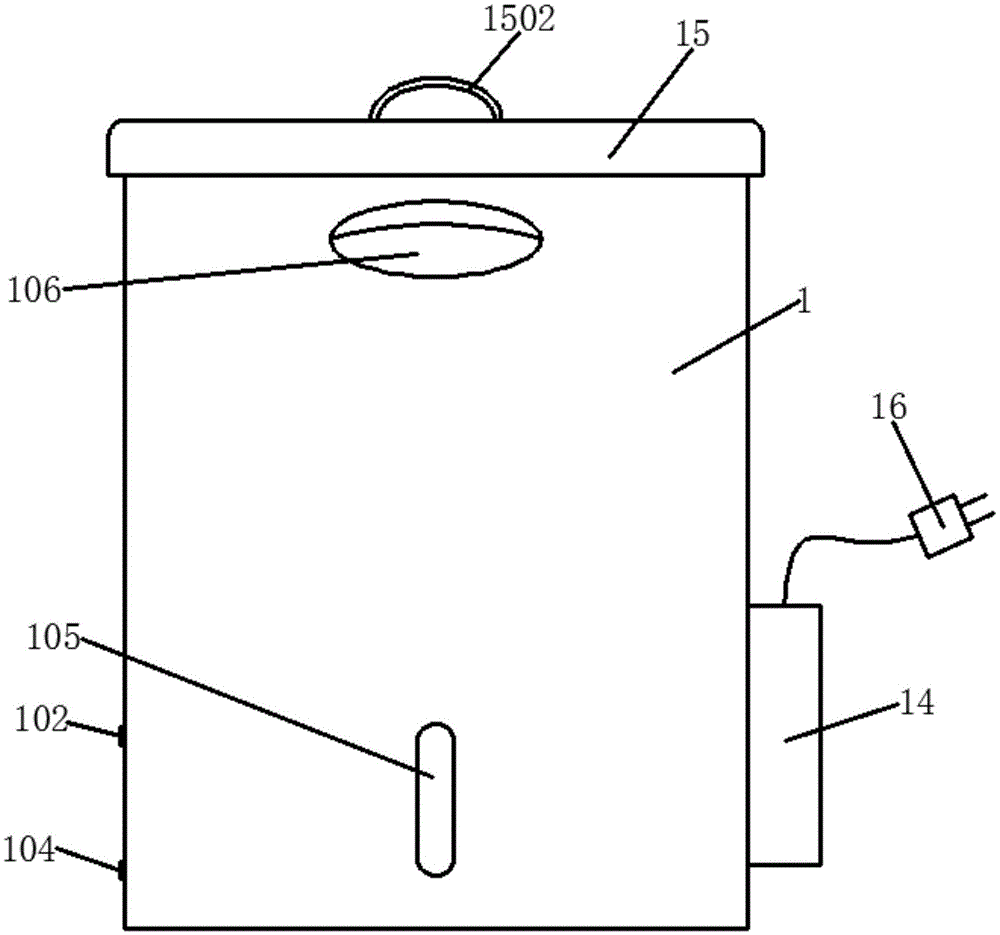
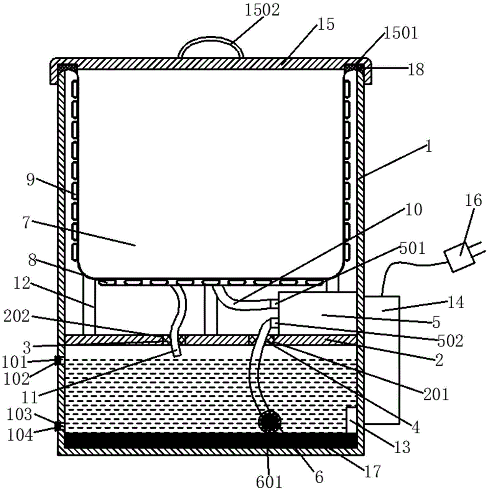
[0018] refer to figure 1 with figure 2 , the present invention is a novel insulation tank, comprising an outer casing 1, a support plate 2, a water pump 5, an insulation tank body 7, a water inlet pipe 10, a water outlet pipe 11, a temperature sensor 13, a controller 14, a cover plate 15 and a heating plate 17 , the inside of the outer shell 1 is provided with a support plate 2; the upper end of the support plate 2 is provided with a water pump 5; A support rod 12 is connected; a bottom hot water pipe 8 is arranged on the bottom surface of the heat preservation barrel body 7, and the bottom surface hot water pipe 8 is located inside the support rod 12; Water pipe 9; the water inlet pipe 10 is connected to the drain pipe 501, and the water outlet pipe 11 is arranged in the inner hole of the second sealing ring 3; a heating plate 17 is arranged on the bottom surface of the outer casing 1, and The wall is provided with a temperature sensor 13; the outer wall of the outer shell...


PUM


Abstract

The invention discloses a novel insulation barrel, comprising an outer shell, an insulation barrel body, a water inlet pipe, a water outlet pipe, a controller, a cover plate and a heating plate; a water suction pump is arranged on an upper end face of a supporting plate inside the outer shell; the insulation barrel body is arranged over the supporting plate and a supporting rod is connected between a bottom surface of the insulation barrel body and the supporting plate; a bottom surface hot water pipe is arranged on the bottom surface of the insulation barrel body; a cylindrical hot water pipe is arranged on an outer cylindrical surface of the insulation barrel body; the water inlet pipe is connected with a drain pipe, while the water outlet pipe is arranged in an inner hole of a second sealing ring; the heating plate is arranged on a bottom surface of the outer shell; a temperature sensor is arranged on an inner sidewall of the outer shell; the controller is arranged on an outer sidewall of the outer shell; and the cover plate is arranged on an upper side of the outer shell; according to the novel insulation barrel, the bottom surface hot water pipe and the cylindrical hot water pipe are arranged on the bottom surface and the side surface of the insulation barrel, respectively, to implement uniform heating to articles in the barrel; further, the novel insulation barrel is simple in structure, good in thermal insulation effect, and convenient to operate, and can be widely popularized and applied.

Description

【Technical field】 [0001] The invention relates to the technical field of thermal insulation containers, in particular to the technical field of thermal insulation barrels. 【Background technique】 [0002] Now, when you go out to eat, you will definitely notice such a phenomenon. Many canteens or restaurants have a special container for rice, some are a large rice cooker, and some are a large thermos bucket. Occasionally, the rice cooker is generally very large, which makes the rice on the top cooler, while the rice on the bottom is hotter, and the rice below often forms a crust. These phenomena all illustrate the irrationality of the rice cooker; At present, the insulation buckets on the market generally include a bucket body and a bucket lid, and the bucket lid is covered on the bucket body. Because the bucket body and the bucket lid of the existing bucket generally adopt a single-layer structure, and the bucket body and the bucket lid of the existing bucket are generally si...

Claims


Application Information

Patent Timeline
Patent Type & Authority Applications(China)
IPC IPC(8): B65D81/18B65D81/24
CPCB65D81/18B65D81/24
Inventor 陈威宇
Owner 徐州茱萸谷生态旅游度假有限公司
Learn More