
Sheet metal part sucking device with clamping lock

A technology of suction device and sheet metal parts, which is applied to conveyor objects, transportation and packaging, conveyors, etc., can solve the problems of unstable adsorption and easy falling off, and achieve the effect of ensuring transportation stability, smooth transportation and simple structure.

Inactive Publication Date: 2016-04-13
SUZHOU HENGTAI METAL PROD
View PDF6 Cites 0 Cited by
  • Summary
  • Abstract
  • Description
  • Claims
  • Application Information

AI Technical Summary

Problems solved by technology

[0003] The technical problem mainly solved by the present invention is to provide a sheet metal suction device with a lock, which has a reasonable design and a simple structure, and solves the problem that the sheet metal material is unstable and easy to fall off when only relying on the adsorption head in the clamping process

Method used


Image

  • Sheet metal part sucking device with clamping lock
  • Sheet metal part sucking device with clamping lock
  • Sheet metal part sucking device with clamping lock

Examples


Embodiment Construction

[0012] The preferred embodiments of the present invention will be described in detail below in conjunction with the accompanying drawings, so that the advantages and features of the present invention can be more easily understood by those skilled in the art, so as to define the protection scope of the present invention more clearly.

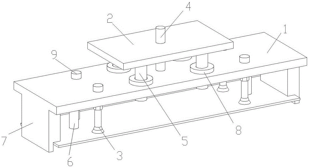
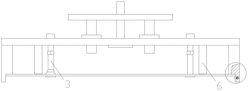
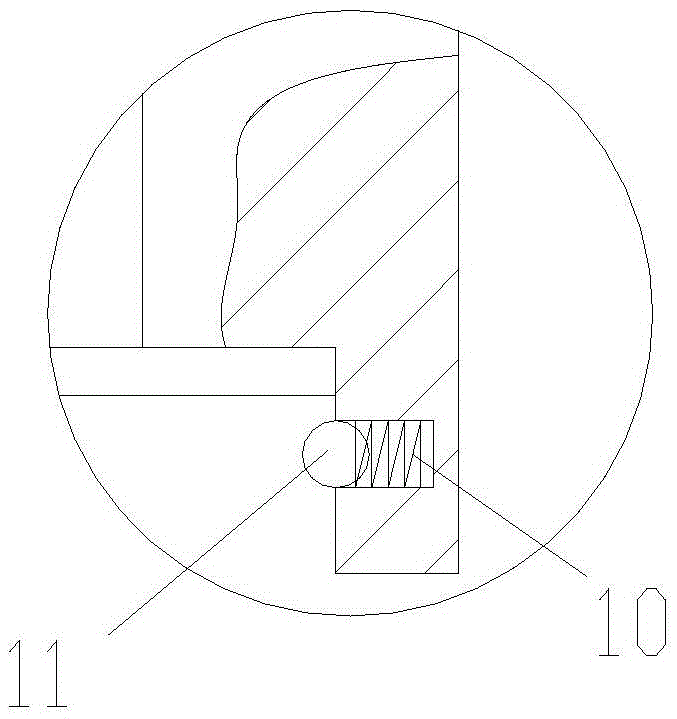
[0013] Please refer to the attached Figures 1 to 3 , the embodiment of the present invention includes:

[0014] A suction device for sheet metal parts with a lock, comprising a fixed frame 1, a lifting seat 2 and an adsorption head 3; the lifting seat 2 is provided with a support rod 4 and a guide rod 5 for connecting the fixed frame 1; the The support rod 4 is located at the center of the lifting base 2 and connected to the fixed frame 1; the guide rod 5 is distributed around the support rod 4 and cooperates with the guide hole on the fixed frame 1; The fixed frame 1 is provided with the suction head 3; the suction head 3 is axially parallel t...


PUM


Abstract

The invention discloses a sheet metal part sucking device with a clamping lock. The sheet metal part sucking device comprises a fixing frame, a lifting seat and adsorbing heads. The lifting seat is provided with a supporting rod and guide rods of the fixing frame. The supporting rod is located in the center of the lifting seat and is connected with the fixing frame. The guide rods are distributed on the periphery of the supporting rod and are matched with guide holes in the fixing frame. The fixing frame is provided with the adsorbing heads which are parallel to the axial direction of the supporting rod. The fixing frame is further provided with limiting rods parallel to the adsorbing heads. The limiting rods are in threaded connection with the fixing frame. The two ends of the fixing frame are further provided with supporting ends perpendicular to the end face of the fixing frame. The supporting ends are provided with grooves sucking sheet metal parts in a matched manner. Containing cavities are formed in the grooves. Outlets of the containing cavities are located in the inner walls of the grooves. Balls and springs are arranged in the containing cavities. The springs eject the balls to the outlets of the containing cavities. Part of ball bodies of the balls are exposed out of the outlets of the containing cavities.

Description

technical field [0001] The invention relates to the field of sheet metal processing equipment, in particular to a sheet metal suction device with a lock. Background technique [0002] The plate vacuum suction control system is a commonly used feeding device on the modern flexible automatic plate machining production line. . At present, the vacuum extraction methods of the plate vacuum suction device are mainly divided into two types. One is to use a vacuum pump or a large vacuum tank to evacuate all the suction cups, that is, to provide a single vacuum source, which is connected to each suction cup through the air pipeline; the other It uses a cylinder piston or a small vacuum tank to vacuumize the suction cups one by one, that is, each suction cup is connected to a set of cylinder piston device or a small vacuum tank, and the suction cup is vacuumed by pushing and pulling the piston through a mechanical device. Contents of the invention [0003] The technical problem ma...

Claims


Application Information

Patent Timeline
Patent Type & Authority Applications(China)
IPC IPC(8): B65G47/91
CPCB65G47/912B65G2201/022
Inventor 卞林元
Owner SUZHOU HENGTAI METAL PROD
Learn More