Back bolt combination device for stone veneer installation and installation method thereof

A technology of combined device and installation method, applied in covering/lining, building, building structure, etc., can solve the problems of high price, limitation, tensile strength limitation, etc., to improve the flexibility of application and improve the convenience of use , the effect of reducing the cost of machinery

Inactive Publication Date: 2016-04-13
百益百利(福州)幕墙工程有限公司
View PDF6 Cites 5 Cited by
  • Summary
  • Abstract
  • Description
  • Claims
  • Application Information

AI Technical Summary

Problems solved by technology

The stone structure used in China mostly uses blind holes on the surface of the material and inserts expansion back bolts with notches. Since the axial dimension of the notch in the expansion part is small, the contact distance between the notch and the blind hole of the material is very short, and the tensile strength is limited. Restrictions, the connecting part of the back bolt is easy to loosen and fall off, causing a safety hazard. At the same time, the expansion type is not easy to disassemble, and the expansion coefficient is high, and the cost is high
Both the traditional percussion type back bolt and the screw-in type back bolt need to be drilled in the corresponding place in advance, and both of them are reamed at the bottom. Since this kind of drilling requires a special machine, one machine costs from four to five thousand to three five In addition, the price of the drill bit used for drilling remains high, which directly increases the cost, especially this kind of back bolt has certain requirements on the thickness ratio of the plate, and the combination of the above factors limits the pace of comprehensive application.

Method used


Image

  • Back bolt combination device for stone veneer installation and installation method thereof
  • Back bolt combination device for stone veneer installation and installation method thereof
  • Back bolt combination device for stone veneer installation and installation method thereof

Examples


Embodiment Construction

[0033] In order to describe the technical content, structural features, achieved goals and effects of the present invention in detail, the following will be described in detail in conjunction with the embodiments and accompanying drawings.

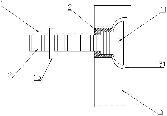
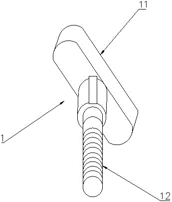
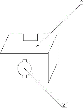
[0034] Please refer to, the back bolt combination device of the present invention includes a T-shaped countersunk head 11, a screw rod 12, a positioning member 2, a nut 13, and a stone veneer 3 provided with a long groove 31 matching the back bolt combination device; The T-shaped countersunk 11 and the screw 12 are a fixed body, referred to as the T-shaped screw 1; the positioning part 2 is provided with a hole 21 for the screw to pass through, and the positioning part 2 enters the T-shaped countersunk 11 through the screw 12 One end is fixedly combined, and the fixed combination is that the combination of the positioning part 2 and the T-shaped screw 1 is provided with a mutual interlocking function, and the described interlocking function...


PUM


Abstract

The present invention discloses a back bolt combination device for stone veneer installation. The back bolt combination device comprises a stone veneer, a T-shaped screw and a positioning piece; the T-shaped screw comprises a T-shaped countersunk head, a screw and a nut matched with the screw; the T-shaped countersunk head and the screw are fixedly connected; the positioning piece is provided with a hole slot or a through hole for allowing the screw to pass through; the positioning piece and the T-shaped screw combination position is provided with a mutual engaging structure; the back of the stone veneer is provided with an elongated slot; two sides of the bottom of the elongated slot are provided with expanded slots which are partial expanded slots or complete expanded slots; the T-shaped countersunk head is inserted into the elongated slot; and the T-shaped countersunk head positioned at the bottom of the elongated slot is rotated into the preset expanded slots by rotating the screw and is capable of moving left and right along the expanded slots. The back bolt combination device can be moved and adjusted left and right according to the opening direction of the elongated slot, and field application flexibility can be largely improved.

Description

technical field [0001] The invention relates to the field of fastening back bolts, in particular to a back bolt combination device for installing stone veneer panels and an installation method thereof. Background technique [0002] The back bolt structure is an installation method that drills a blind hole at a certain position from the surface of the material, puts the back bolt into the blind hole, and makes the back bolt and the material tightly connected. The stone structure used in China mostly uses blind holes on the surface of the material and inserts expansion back bolts with notches. Since the axial dimension of the notch in the expansion part is small, the contact distance between the notch and the blind hole of the material is very short, and the tensile strength is limited. Restrictions, the joints of the back tie are easy to loosen and fall off, causing potential safety hazards, and the expansion type is not easy to disassemble, and the expansion coefficient is h...

Claims


Application Information

Patent Timeline
Patent Type & Authority Applications(China)
IPC IPC(8): E04F13/23
Inventor 李诗全
Owner 百益百利(福州)幕墙工程有限公司
Why Eureka
Try Eureka