Compressor stall test structure and test method based on dynamic pressure measurement

A technology of dynamic pressure and test method, applied in the direction of engine control, machine/engine, mechanical equipment, etc., can solve the problems of no discovery, increased cost, and complicated difficulty, and achieve the effect of simple structure, easy realization and easy realization.

Active Publication Date: 2017-05-10
CHINA NORTH ENGINE INST TIANJIN
View PDF6 Cites 0 Cited by
  • Summary
  • Abstract
  • Description
  • Claims
  • Application Information

AI Technical Summary

Problems solved by technology

[0004] Some foreign scholars used dynamic pressure combined with blade vibration to conduct stall test. Due to the increase of blade vibration measurement in the method, the cost increased and the difficulty tended to be complicated. Obtained on the Internet, many have also carried out model abstraction, such as changing the diffuser and volute structure, etc.; no public information about the stall measurement on the turbocharger centrifugal compressor prototype was found

Method used


Image

  • Compressor stall test structure and test method based on dynamic pressure measurement
  • Compressor stall test structure and test method based on dynamic pressure measurement
  • Compressor stall test structure and test method based on dynamic pressure measurement

Examples


Embodiment Construction

[0020] It should be noted that, in the case of no conflict, the embodiments of the present invention and the features in the embodiments can be combined with each other.

[0021] The present invention will be described in detail below with reference to the accompanying drawings and examples.

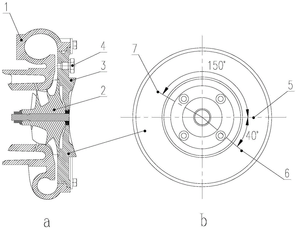
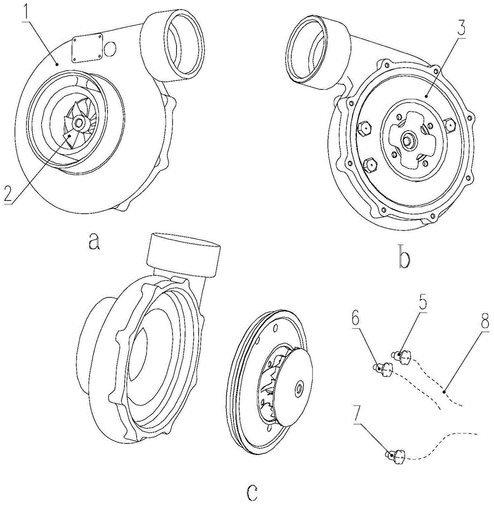
[0022] Compressor stall test structure based on dynamic pressure measurement, such as figure 1 As shown, it includes a compressor volute 1, a compressor impeller 2, a compressor back plate 3, and a sensor 4. The compressor volute 1 is fixed on the compressor back plate 3 through bolts and pressure plates, and the compressor impeller 2 passes through the rotating shaft The shaft end nut is fixed on the rotating shaft, and the rotating shaft cooperates with the compressor back plate 3 through a sealing structure and is connected with the bearing seat; the compressor impeller 2 is clearance fit with the compressor back plate 3 and the compressor volute 1.

[0023] The middle part of the si...


PUM


Abstract

The invention provides a gas compressor stalling test structure based on dynamic pressure measurement. The gas compressor stalling test structure comprises a gas compressor volute, a gas compressor impeller, a gas compressor back disc and sensors; the gas compressor volute is fixed to the gas compressor back disc, the gas compressor impeller is fixed to a rotating shaft, the rotating shaft and the gas compressor back disc are matched through a sealing structure, and the rotating shaft is connected with a bearing base; a plurality of sensor bases where the sensors are installed are distributed in the middle portion of the side wall of a pressure expander of the gas compressor back disc in the circumferential direction; and the sensors are high-frequency response dynamic pressure sensors, and pressure testing holes are formed in the sensor bases. The gas compressor stalling test structure has the advantages that based on the wall face static testing means easy to achieve and implement, the multiple dynamic pressure test sensors are distributed on gas compressor static pieces in the circumferential direction, change features of the wall face static pressure along with time are obtained, stalling generation conditions and features of the centrifugal gas compressor are captured, and prototype gas compressor stalling testing is completed with smaller investment.

Description

technical field [0001] The invention belongs to the technical field of centrifugal compressor testing, in particular to a compressor stall testing structure based on dynamic pressure measurement. Background technique [0002] Turbocharged engines can improve fuel economy and reduce emissions. With energy shortages and increasingly stringent environmental regulations and emission requirements, turbocharged engines are facing new challenges and a broad market. The enhanced power density of turbocharged engines for vehicles, EGR, SCR and other exhaust system treatment devices that meet emission requirements, and the adaptability to variable altitude environments have put forward the requirements for centrifugal compressors with high pressure ratio and wide stable working range. However, with the increase of the boosting ratio, the internal flow of the centrifugal compressor tends to be complicated, and its stable working range narrows sharply, and the efficiency decreases. It i...

Claims


Application Information

Patent Timeline
Patent Type & Authority Patents(China)
IPC IPC(8): F04D27/00
CPCF04D27/001F05D2270/022F05D2270/101
Inventor 李书奇庄丽侯琳琳刘畅黄磊张继忠张俊跃邢卫东
Owner CHINA NORTH ENGINE INST TIANJIN
Why Eureka
Try Eureka