
Built-in pump LNG (liquefied natural gas) storage tank

A storage tank and pump well technology, applied in the field of LNG storage equipment, can solve the problems of wasting resources and maintenance time, unable to replace the valve core and valve seat seal, non-removable, etc., to achieve long service life, reduce maintenance costs and time, fatigue reduction effect

Inactive Publication Date: 2016-04-13
HOPE CLEAN ENERGY (GRP) CO LTD
View PDF8 Cites 1 Cited by
  • Summary
  • Abstract
  • Description
  • Claims
  • Application Information

AI Technical Summary

Problems solved by technology

[0003] In the current industry, the built-in pump LNG storage tank is to place the LNG submersible pump directly inside the storage tank. During maintenance and replacement, the internal medium of the storage tank needs to be emptied and cleaned before maintenance or replacement, which wastes a lot of resources and maintenance time ;The bottom hole valve of LNG storage tank with bottom hole valve cannot be disassembled, and the valve core and valve seat seal cannot be replaced

Method used


Image

  • Built-in pump LNG (liquefied natural gas) storage tank
  • Built-in pump LNG (liquefied natural gas) storage tank
  • Built-in pump LNG (liquefied natural gas) storage tank

Examples


specific Embodiment

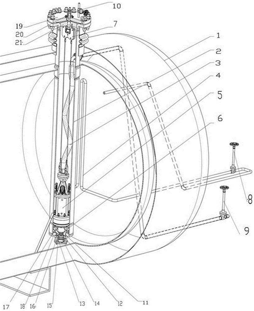
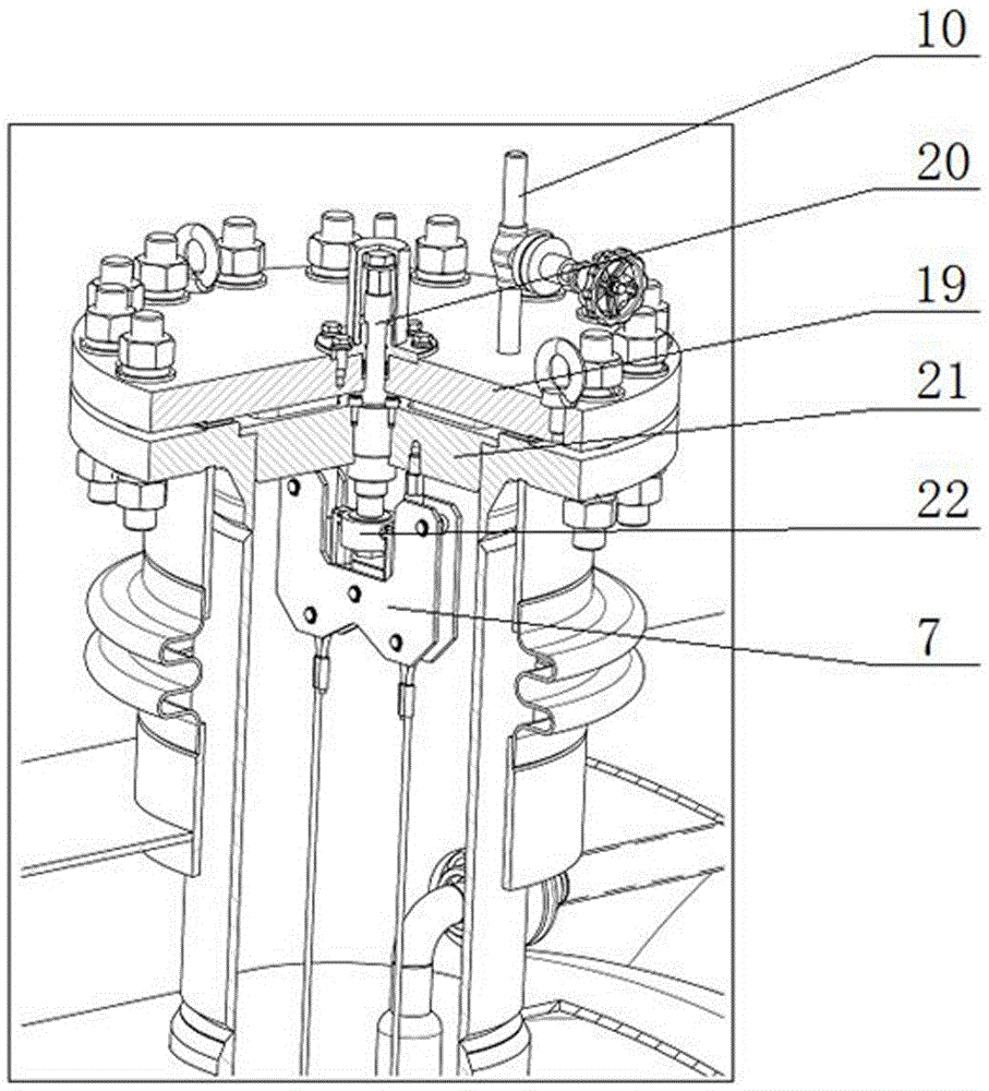
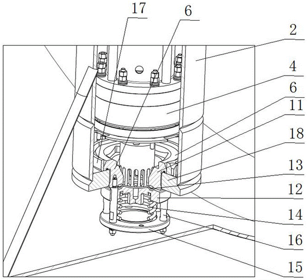
[0034] like Figure 1-3 As shown, the LNG storage tank with built-in pump of the present invention includes an LNG storage tank body 1 and a pump well 2. The pump well 2 is connected to the LNG storage tank body 1 and extends into the LNG storage tank body 1, and is located in the pump well 2. An LNG submersible pump 5 is provided, one end of the liquid outlet hose 3 is connected to the LNG submersible pump 5, and the other end of the liquid outlet hose 3 should be connected to the outside of the pump well 2; And lift the hoisting mechanism of the LNG submersible pump 5 and the pump well flange cover 19 for sealing the pump well 2; a pump well bottom valve 6 is provided at the bottom of the pump well 2, and the pump well bottom valve 6 includes a valve seat 11, a valve The core 12 and the spring seat 15, the spring seat 15 is fixedly connected to the valve seat 11 through the valve core guide post 16, the valve core 12 is sleeved on the valve core guide post 16 and is pressed ...

specific Embodiment 2

[0044] According to the LNG storage tank with built-in pump described in Embodiment 1, the disassembly method of its LNG submersible pump 5:

[0045] Step 1: Rotate the operating screw 20 to make the LNG submersible pump 5 rise until the valve core 12 of the pump bottom valve 6 is fitted and sealed with the valve seat 11 under the action of the elastic force of the spring 14, and then the pressure at the outlet of the LNG storage tank body 1 is detected. To confirm that the pump bottom valve 6 is closed;

[0046] Step 2: Pour nitrogen or inert gas into the pump well 2 to remove the LNG liquid in the pump well 2;

[0047] Step 3: Close the valves connected to the LNG storage tank body 1, disassemble the pump well flange cover 19, lift the LNG submersible pump 5 along the pump well 2, and then replace or disassemble the lifted LNG submersible pump 5 .

[0048] Due to the above method, it can ensure that the LNG submersible pump 5 can be quickly disassembled for easy replacemen...

specific Embodiment 3

[0049] According to the LNG storage tank with built-in pump described in Embodiment 1, the assembling method of its LNG submersible pump 5:

[0050] Step 1: Check that the valves connected to the LNG storage tank body 1 are indeed closed, seal the pump well flange 19 on the pump well 2, and introduce nitrogen or inert gas into the pump well 2 to clean the pump well 2. Purging, then venting nitrogen or inert gas;

[0051] Step 2: Open the pump well flange cover 19, hoist the LNG submersible pump 5 into the pump well 2, then cover the pump well flange cover 19 again and confirm that the pump well 2 is sealed;

[0052] Step 3: Rotate the screw 20 to make the LNG submersible pump 5 descend, and the LNG submersible pump 5 pushes the valve core 12 under the action of gravity to open the pump bottom valve 6, open the valves connected to the LNG storage tank body 1, and detect. Check the pressure at the outlet of the LNG storage tank body 1 and confirm that the pump bottom valve 6 is...


PUM


Abstract

The invention relates to a built-in pump LNG (liquefied natural gas) storage tank, belongs to the field of LNG storage devices, and discloses the built-in pump LNG storage tank. The built-in pump LNG storage tank comprises an LNG storage tank body and a pump well, wherein the pump well is connected on the LNG storage tank body, and stretches into the LNG storage tank body; an LNG immersed pump is arranged in the pump well; one end of a liquid outlet hose is connected on the LNG immersed pump, and the other end of the liquid outlet hose is communicated to the outer part of the pump well; a hoisting mechanism used for hoisting and lifting the LNG immersed pump and a pump well blind flange used for sealing the pump well are arranged at the opening part of the pump well; a pump well bottom valve is arranged at the bottom of the pump well; the pump well bottom valve comprises a valve seat, a valve core and a spring seat; the spring seat is fixedly connected with the valve seat through a valve core guide pillar; the valve core is arranged on the valve core guide pillar in a sleeving manner, and is propped against the spring seat through a spring; the valve seat and the valve core are sealed through a valve seat sealing element; and the valve core of the pump well bottom valve is pushed open under the gravity action of the LNG immersed pump, or is closed under the elastic action of the spring.

Description

technical field [0001] The invention relates to an LNG storage tank with a built-in pump, belonging to the field of LNG storage equipment. Background technique [0002] LNG (LiquefiedNaturalGas), the English abbreviation of liquefied natural gas. Natural gas is a combustible gas that is naturally mined in gas fields, and its main component is methane. LNG is condensed into liquid by cooling gaseous natural gas to -162°C under normal pressure. Liquefied natural gas can greatly save storage and transportation space and cost, and has the characteristics of large calorific value and high performance. LNG is a clean and efficient energy source. Because importing LNG helps energy consuming countries to diversify energy supply and ensure energy security, while exporting LNG helps natural gas producing countries to effectively develop natural gas resources, increase foreign exchange income, and promote national economic development, LNG trade is becoming a global energy market. ...

Claims


Application Information

Patent Timeline
Patent Type & Authority Applications(China)
IPC IPC(8): F17C1/00F16K1/00F16K31/44F17C13/00B66F11/00
CPCF16K1/00B66F11/00F16K31/44F17C13/00
Inventor 江涛杨国柱甘鹏罗军魏瑛武佳慧卢荣李俊阳何维良周大明
Owner HOPE CLEAN ENERGY (GRP) CO LTD
Learn More