Methane gas recycling system and control method
A recovery system, methane gas technology, applied in the direction of refrigeration and liquefaction, liquefaction, solidification, etc., can solve the problem that the compressor cannot run safely and stably, and achieve the effect of preventing pressure from being suppressed
- Summary
- Abstract
- Description
- Claims
- Application Information
AI Technical Summary
Problems solved by technology
Method used
Image

Examples
Embodiment 1
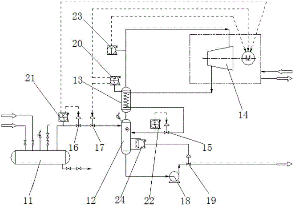
[0023] Such as figure 1 As shown, this embodiment provides a methane gas recovery system, the system includes a methane storage tank 11, the gas outlet of the methane storage tank 11 is connected to the inlet of the flasher 12 through a pipeline, and the flasher 12 The gas outlet of the gas is connected to the compression device 14 through the heat exchange device 13, and the heat exchange device 13 is connected to the return port of the flash evaporator 12 through a throttle valve 15, and the liquid outlet of the flash evaporator 12 is connected to the methane The air inlet of the storage tank 11 is connected, a pressure self-regulating valve 17 is provided between the methane storage tank 11 and the flash evaporator 12, and the inlet of the compression device 14 is provided with a pressure self-regulating valve 17 to control the pressure self-regulating valve 17 and the The first pressure interlock device 20 for opening and closing the compression device 14.
[0024] The ab...
Embodiment 2
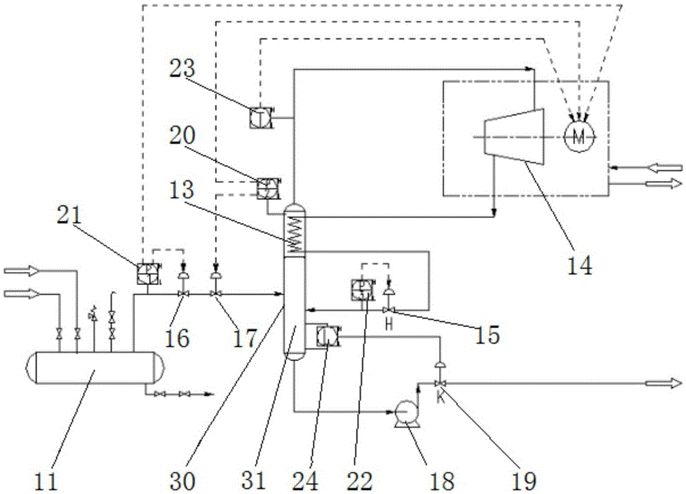
[0035] This embodiment is a deformation on the basis of Embodiment 1, and the difference from Embodiment 1 is that the flash evaporator in the methane gas recovery system described in this embodiment is a flash evaporator with heat exchange, which will be described in detail below:
[0036] Such as figure 2 As shown, the flash evaporator with heat exchange includes a tank body 30, the tank body 30 is provided with a gas-liquid separation device 31 located at the bottom of the tank body and a heat exchange device 13 located at the top of the tank body, the heat exchange device 13 includes at least two passages, wherein the first passage communicates with the first air inlet on the tank body 30 for receiving gas, and the second passage communicates with the second air inlet on the tank body 30, wherein The second air inlet is connected to the compression device 14 through the first air outlet at the top of the tank body 30 , and a liquid outlet is provided at the bottom end of ...
Embodiment 3
[0041] This embodiment provides a methane gas recovery control method, using the methane gas recovery system described in any one of embodiment 1 or embodiment 2 to recover methane gas and collect methane liquid, the steps are as follows: step S1: the methane to be recovered The gas is collected and buffered, and when the collected methane gas reaches the first preset amount, enter step S2; when the collected methane gas is lower than the second preset amount, continue to collect methane gas until the methane gas reaches the first preset amount amount, enter step S2; step S2: after the heat exchange and temperature rise of the methane gas, enter the compression process to form high-pressure methane gas, and monitor the pressure of the methane gas at the compression inlet. 14 methane gas volume, when the pressure is lower than the pressure low value, increase the methane gas volume entering the compression device 14; step S3: heat exchange and cool down the high-pressure methane...
PUM
 Abstract
Description
Claims
Application Information
 - R&D
- Intellectual Property
- Life Sciences
- Materials
- Tech Scout
- Unparalleled Data Quality
- Higher Quality Content
- 60% Fewer Hallucinations
Browse by: Latest US Patents, China's latest patents, Technical Efficacy Thesaurus, Application Domain, Technology Topic, Popular Technical Reports.
© 2025 PatSnap. All rights reserved.Legal|Privacy policy|Modern Slavery Act Transparency Statement|Sitemap|About US| Contact US: help@patsnap.com