Supercharge Your Innovation With Domain-Expert AI Agents!

Dryers for fiber production

A dryer and fiber technology, applied in non-progressive dryers, dryers, drying chambers/containers, etc., can solve the problem of incapable fiber surface oiling agent treatment, etc., and achieve good drying effect and compact structure.

Active Publication Date: 2017-08-22
浙江金旗新材料科技有限公司
View PDF1 Cites 0 Cited by
  • Summary
  • Abstract
  • Description
  • Claims
  • Application Information

AI Technical Summary

Problems solved by technology

[0003] The invention provides a swing-drying dryer for fiber production capable of surface oil treatment, which solves the problem that the existing dryer cannot perform surface oil treatment on fibers

Method used


Image

  • Dryers for fiber production
  • Dryers for fiber production
  • Dryers for fiber production

Examples


Embodiment 1

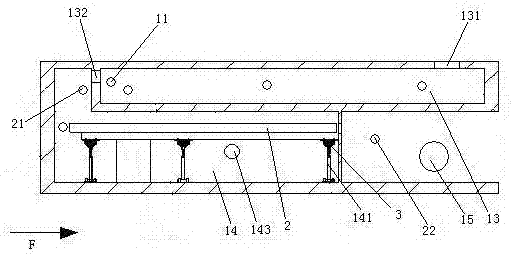
[0029] Embodiment one, see figure 1 , a dryer for fiber production, comprising a shell 1. An oil agent chamber 13 and a drying chamber 14 are sequentially arranged in the housing 1 from top to bottom. The oil chamber 13 is provided with an inlet hole 131 and an outlet hole 132 . Several first guide rollers 11 are arranged in the oil chamber 13 . A wire winding machine 15 is also provided in the casing 1 . The wire winding machine 15 is located on the right side of the drying chamber 14 .

[0030] The drying chamber 14 is provided with a support pendulum 141, a drying cylinder 2 and a heating mechanism for heating the drying cylinder. The heating mechanism 142 is an electric heating wire arranged in the drying drum 2 . An exhaust port 143 is provided in the drying chamber 14 .

[0031] The drying drum 2 is swingably supported in the drying chamber 14 by at least two support swing rods 141 . The upper end of the support swing rod 141 is connected with the drying cylinder ...

Embodiment 2

[0044] Embodiment two, the difference with embodiment one is:

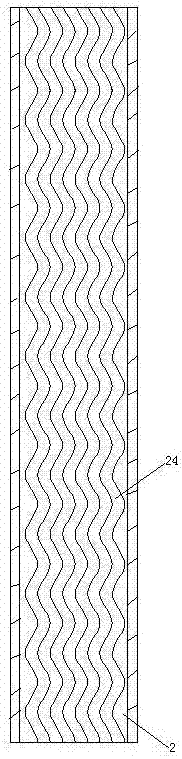
[0045] see Figure 10 , The bottom wall of the drying cylinder 2 is provided with an inner cavity 25 . The inner cavity 25 is provided with an air outlet hole 26 penetrating into the drying cylinder 2 . The top wall of the drying cylinder 2 is provided with vent holes 27 .

[0046] The air outlet hole 26 is staggered with the anti-slip groove 24, which can more effectively promote the fibers to roll under the action of the anti-slip groove. The inner chamber 25 is provided with a roller 9 . The roller 9 is a tubular structure. An accelerator lever 91 is arranged in the roller 9 . The acceleration lever 91 can accelerate the rolling of the roller 9 in the inner cavity 25 . The extension direction of the roller shaft 9 is the same as that of the drying cylinder 2 .

[0047] see Figure 11 , A plurality of air grooves 92 are provided on the peripheral surface of the roller 9 . The air grooves 92 extend axial...


PUM


Abstract

The invention relates to equipment for fiber production. A dryer for fiber production comprises a shell; a wire winding machine, an oil agent cavity and a drying chamber are arranged in the shell; the oil agent cavity is provided with a feed hole and a discharge hole; a support swing rod, a drying cylinder supported in the drying chamber through the support swing rod, a swing mechanism for driving the drying cylinder to swing and a heating mechanism for heating the drying cylinder are arranged in the drying chamber; the extending direction of the drying cylinder is intersected with the swing direction; one end of the drying cylinder is in butt joint with the discharge hole, and the other end is in butt joint with the wire winding machine; the swing mechanism includes a connecting rod, a turntable and a motor for driving the turntable to move; one end of the connecting rod is hinged to the turntable, and the other end is hinged with the drying cylinder; and the hinged point between the connecting rod and the turntable is deviated from the axis of the turntable. The swing drying dryer for fiber production capable of performing surface oil agent treatment, provided by the invention, solves the problem of incapability of performing the surface oil agent treatment for fibers in a traditional dryer.

Description

technical field [0001] The invention relates to equipment for fiber production, in particular to a dryer for fiber production. Background technique [0002] In the process of fiber production, the fiber needs to be treated with oil agent and dried. Existing dryers for drying fibers are not integrated with the oil refueling mechanism and are vacuum-dried. A kind of existing drying machine is disclosed in the patent document whose Chinese patent application number is ZL2014103372805, the announcement number is CN104132516A, and the name is "a drum dryer for drying fiber fabrics". Contents of the invention [0003] The invention provides a swing-drying dryer for fiber production capable of surface oil treatment, which solves the problem that the existing dryer cannot perform surface oil treatment on fibers. [0004] The above technical problems are solved by the following technical solutions: a dryer for fiber production, including a casing, a wire winding machine, an oil c...

Claims


Application Information

Patent Timeline
Patent Type & Authority Patents(China)
IPC IPC(8): F26B11/02F26B25/16F26B23/06
CPCF26B11/022F26B23/06F26B25/16
Inventor 金光琦
Owner 浙江金旗新材料科技有限公司
Features
  • R&D
  • Intellectual Property
  • Life Sciences
  • Materials
  • Tech Scout
  • Unparalleled Data Quality
  • Higher Quality Content
  • 60% Fewer Hallucinations
Learn More