Mobile robot homing control system

A mobile robot, control system technology, applied in control/regulation systems, non-electric variable control, two-dimensional position/channel control, etc., can solve problems such as extra cost, measurement angle error, expensive hardware support, etc.

Inactive Publication Date: 2016-04-13
林盛增
View PDF6 Cites 3 Cited by
  • Summary
  • Abstract
  • Description
  • Claims
  • Application Information

AI Technical Summary

Problems solved by technology

[0003] The method based on the infrared receiver and gyroscope needs to use the heading angle provided by the gyroscope when adjusting the attitude of the robot. The gyroscope sensor itself drifts, and the measurement angle will produce errors. Even if there is a magnetometer for correction, complex Kalman is required. Filtering algorithm, when there is external magnetic field interference, the measurement error will be greater
[0004] In the method based on infrared and visual sensors, the image collected by vision is used to process the robot's posture. Although the image processing theory is very mature, it requires expensive hardware support and high cost of use.
In the method based on the infrared receiver, using the infrared receiver and peripheral auxiliary devices to guide the robot to return to the charging position requires additional costs; or using the infrared receiver to guide the robot, which can contact the charging stand at any angle, but for indoor robots Said that considering the limitation of charging space, it is necessary to specify the relative angle between the robot and the charging stand; use the infrared receiver and the odometer to calculate the infrared range emitted by the charging stand, use the odometer to calculate the moving distance of itself, and then adjust the distance between the robot and the charging stand. The charging process of this method is complicated and the efficiency is not high

Method used


Image

  • Mobile robot homing control system
  • Mobile robot homing control system
  • Mobile robot homing control system

Examples


Embodiment Construction

[0018] The following will clearly and completely describe the technical solutions in the embodiments of the present invention with reference to the accompanying drawings in the embodiments of the present invention. Obviously, the described embodiments are only some, not all, embodiments of the present invention. Based on the embodiments of the present invention, all other embodiments obtained by persons of ordinary skill in the art without creative efforts fall within the protection scope of the present invention.

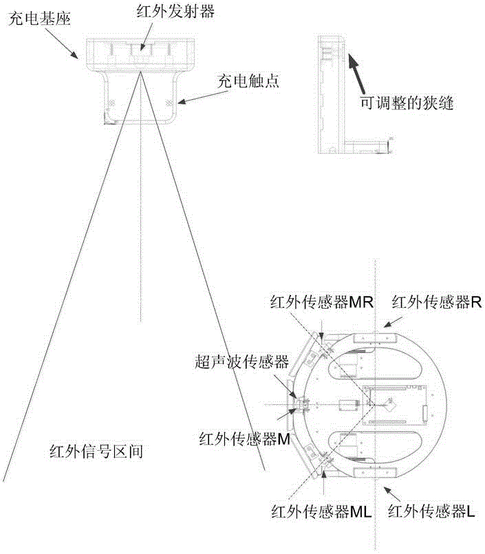
[0019] See figure 1 , the mobile robot homing control system provided by the embodiment of the present invention includes: an infrared transmitter, arranged inside the charging base, used to generate a fan-shaped infrared signal area; five infrared receivers, used to detect the infrared emission The signal emitted by the transmitter includes two infrared receivers located on both sides of the robot, and three infrared receivers located at the front of the robot; on...


PUM


Abstract

The invention provides a mobile robot homing control system. The mobile robot homing control system includes an infrared emitter arranged in a charging base, five infrared receivers which are used for detecting signals emitted by the infrared emitter and comprise two infrared receivers located at two sides of a robot, and three infrared receivers located at the front part of the robot, an ultrasonic sensor used for detecting a distance between the robot and the charging base, a moving mechanism used for driving the robot to move or rotate, and a main controller used for controlling the moving mechanism to act according to the distance detected by the ultrasonic sensor and the conditions of the signals of the infrared emitter which are received by the five infrared receivers so as to drive the robot to swerve or advance. With the mobile robot homing control system adopted, fast and stable automatic homing charging of the mobile robot can be realized.

Description

technical field [0001] The invention relates to the technical field of mobile service robots, in particular to a mobile robot homing control system. Background technique [0002] An electric-driven mobile robot with autonomous behavior may encounter low battery power when performing tasks continuously. At this time, it needs to autonomously return to the charging base to replenish power. For home service robots, the rear must enter the charging base, and the robot can still perform visual security detection tasks during the charging process. At present, there are mainly several automatic homing charging methods: based on infrared receivers and gyroscopes; based on infrared receivers and visual sensors; and based on infrared receivers. [0003] The method based on the infrared receiver and gyroscope needs to use the heading angle provided by the gyroscope when adjusting the attitude of the robot. The gyroscope sensor itself drifts, and the measurement angle will produce erro...

Claims


Application Information

Patent Timeline
Patent Type & Authority Applications(China)
IPC IPC(8): G05D1/02G05D1/12H02J7/00
CPCG05D1/0229G05D1/0242G05D1/0255G05D1/12H02J7/00
Inventor 林盛增
Owner 林盛增
Why Eureka
Try Eureka