Shift register unit, driving method thereof and shift register

A shift register unit and output unit technology, applied in static memory, digital memory information, instruments, etc., can solve the problems of limited drive capability of clock signal CK1, large delay, increased short-circuit power consumption, etc., to achieve narrow borders, Reduce the number and avoid the effect of signal delay

Active Publication Date: 2018-06-29
WUHAN TIANMA MICRO ELECTRONICS CO LTD +1
View PDF6 Cites 0 Cited by
  • Summary
  • Abstract
  • Description
  • Claims
  • Application Information

AI Technical Summary

Problems solved by technology

[0005] However, due to the limited driving capability of the clock signal CK1, when the output load is large (for example, the number of pixels contained in the pixel row to be driven is large), using the clock signal CK1 to drive will generate a large delay, which will lead to short-circuit power increase in consumption

Method used


Image

  • Shift register unit, driving method thereof and shift register
  • Shift register unit, driving method thereof and shift register
  • Shift register unit, driving method thereof and shift register

Examples


Embodiment Construction

[0027] The application will be further described in detail below in conjunction with the accompanying drawings and embodiments. It should be understood that the specific embodiments described here are only used to explain related inventions, rather than to limit the invention. It should also be noted that, for ease of description, only parts related to the invention are shown in the drawings.

[0028] It should be noted that, in the case of no conflict, the embodiments in the present application and the features in the embodiments can be combined with each other. The present application will be described in detail below with reference to the accompanying drawings and embodiments.

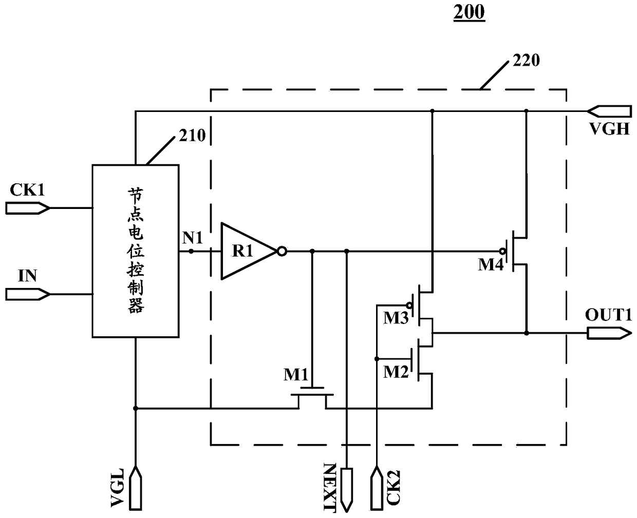
[0029] see figure 2Shown is a schematic circuit structure diagram 200 of a shift register unit according to an embodiment of the present application.

[0030] figure 2 The shift register unit shown includes a node potential controller 210 and an output unit 220 .

[0031] The node potential c...


PUM


Abstract

The invention discloses a shift register unit and a driving method thereof, and a shift register. The shift register unit comprises a node potential controller and an output unit; the node potential controller is used for generating node potential signals on the basis of first voltage signals of a first voltage input end and second voltage signals input by a second voltage input end under the control of first clock signals input by a first clock signal end and displacement voltage signals input by a displacement signal end; and the output unit is used for generating first output signals of the shift register unit on the basis of the first voltage signals of the first voltage input end and the second voltage signals input by the second voltage input end under the control of the node voltage signals and second clock signals input by a second clock signal end. According to the scheme provided by the invention, the driving capability is high, and node voltages are stable.

Description

technical field [0001] The present disclosure generally relates to display technology, and in particular, to a shift register unit, a driving method thereof, and a shift register. Background technique [0002] In a display device, a shift register generally includes a plurality of cascaded shift register units, and each shift register unit sends a driving signal to a row (or column) of pixels in a display panel of the display device, so as to be connected to the row (or column) or column) the transistors connected to each pixel are turned on or off. [0003] see figure 1 Shown is a schematic circuit structure diagram 100 of a shift register unit in an existing shift register. [0004] figure 1 The shift register unit in includes a node potential controller 110 and an output unit 120 . The output unit 120 is driven by the clock signal CK1. That is to say, the output unit 120 provides the clock signal CK1 to the output terminal OUT under the control of the node potential ...

Claims


Application Information

Patent Timeline
Patent Type & Authority Patents(China)
IPC IPC(8): G09G3/20
CPCG09G3/20G11C19/28
Inventor 邹文晖钱栋吴桐张通
Owner WUHAN TIANMA MICRO ELECTRONICS CO LTD
Why Eureka
Try Eureka