

L-shaped sub-array utilization method
A technology of shape sub-array and antenna sub-array, which is applied in the application field of L-shaped sub-array to achieve the effect of wide application range, small scale and non-single array form.
- Summary
- Abstract
- Description
- Claims
- Application Information
AI Technical Summary
Problems solved by technology
Method used
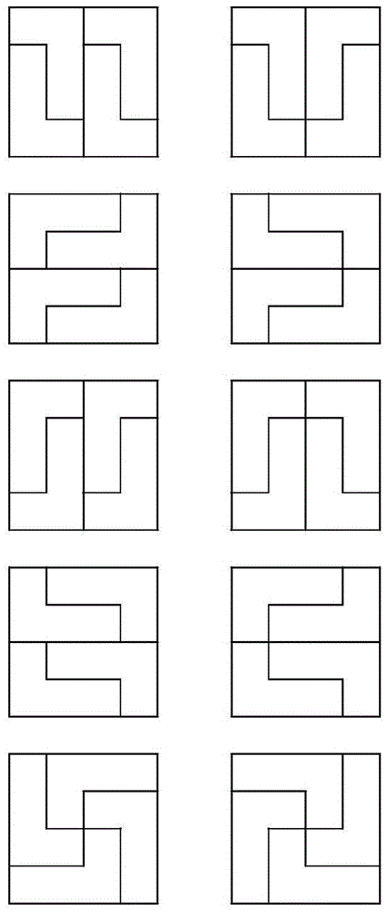
Image

Examples
Embodiment 1
[0064] see Figure 6 , splicing the square sub-array modules into a 12*20 rectangular antenna array by randomly selecting them from the equipment library. Each square antenna sub-array module has a total of 4*4 antenna elements, so 15 modules are required. After determining the layout scheme of the rectangular antenna array, select one of the above five phase centers as the phase center of the L-shaped sub-array of the rectangular antenna array.
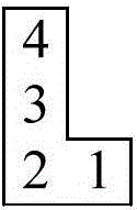
[0065] see Figure 9-10 , the figure is the direction diagram of the angle of view of the two main tangent planes of the rectangular antenna array at the antenna element spacing λ / 2 (half the working wavelength), and the phase center is taken as Figure 4 In 4a—the No. 1 antenna element of the L-shaped sub-array is used as the phase center of the L-shaped sub-array. Theoretically, the spacing between subarrays is equal to 1 wavelength, which is greater than the theoretical unit spacing where no grating lobes can be detected by pat...
Embodiment 2
[0067] Similar to Embodiment 1, a 16*16 square antenna array is assembled by using the square sub-array modules in the equipment library. Each square antenna sub-array module has 4*4 antenna elements, so 16 modules are required.
[0068] see Figure 11-12 , the figure is the direction diagram of the angle of view of the two main tangent planes of the square antenna array at the antenna element spacing λ / 2 (half the working wavelength), and the phase center is taken as Figure 4 In 4a—the No. 1 antenna element of the L-shaped sub-array is used as the phase center of the L-shaped sub-array. Theoretically, if the spacing between sub-arrays is greater than 1 wavelength, grating lobes will appear after pattern scanning, but no grating lobes can be seen in the calculation results.
Embodiment 3
[0070] Similar to Embodiment 1, a circular antenna array is assembled by using the square sub-array modules in the equipment library. The circular antenna array requires 13 modules.
[0071] see Figures 13 to 14 , the figure is the direction diagram of the angle of view of the two main tangent planes of the rectangular array at the antenna element spacing λ / 2 (half the working wavelength), and the phase center is taken as Figure 4 In 4a—the No. 1 antenna element of the L-shaped sub-array is used as the phase center of the L-shaped sub-array. Theoretically, if the spacing between sub-arrays is greater than 1 wavelength, grating lobes will appear after pattern scanning, but no grating lobes can be seen in the calculation results.
PUM
 Abstract
Description
Claims
Application Information