
Low-profile GSM-LTE coplanar directional antenna

A directional antenna, low profile technology, applied in the LTE coplanar directional antenna, low profile GSM field, to achieve the effect of low profile, compact structure, eliminating the need for feeder network

Active Publication Date: 2016-04-13
NANJING HOWKING COMM TECH
View PDF13 Cites 6 Cited by
  • Summary
  • Abstract
  • Description
  • Claims
  • Application Information

AI Technical Summary

Problems solved by technology

The antenna design scheme in traditional mobile terminals cannot meet the new application requirements, so the antenna design has become a difficult problem in the implementation of new application systems

Method used


Image

  • Low-profile GSM-LTE coplanar directional antenna
  • Low-profile GSM-LTE coplanar directional antenna
  • Low-profile GSM-LTE coplanar directional antenna

Examples


Embodiment Construction

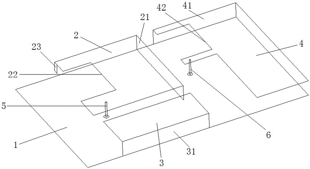
[0025] like figure 1 As shown, the present invention discloses a low-profile GSM and LTE coplanar directional antenna, which includes a metal reflector 1, and the low-profile GSM and LTE coplanar directional antenna also includes an LTE radiation unit patch 2 and an LTE radiation unit parasitic patch 3 , GSM radiation unit patch 4, LTE radiation unit feed structure 5 and GSM radiation unit feed structure 6, LTE radiation unit patch 2, LTE radiation unit parasitic patch 3 and GSM radiation unit patch 4 are all located on the metal reflector 1, the LTE radiating unit patch 2 includes a first grounding edge 21, the LTE radiating unit parasitic patch 3 includes a second grounding edge 31, the GSM radiating unit patch 4 includes a third grounding edge 41, and the first grounding edge 21 , the second grounding edge 31 and the third grounding edge 41 are vertically installed on the metal reflector 1 . Among them, the first grounding edge 21, the second grounding edge 31 and the thir...


PUM


Abstract

The invention relates to the technical field of microstrip antennas, in particular to a low-profile GSM-LTE coplanar directional antenna. The low-profile GSM-LTE coplanar directional antenna comprises a metal reflecting plate, an LTE radiating element patch, an LTE radiating element parasitic patch, a GSM radiating element patch, an LTE radiating element feed structure and a GSM radiating element feed structure. According to the low-profile GSM-LTE coplanar directional antenna, the LTE radiating element patch, the LTE radiating element parasitic patch and the GSM radiating element patch are arranged on the metal reflecting plate in a coplanar manner. The low-profile GSM-LTE coplanar directional antenna is in directional radiation, simultaneously supports a GSM band and an LTE band, has a low profile and a simple structure when obtaining a wide working band, is directly fed by a coaxial feeder line; a complicated feed network is omitted; and design and installation are facilitated.

Description

technical field [0001] The invention relates to the technical field of microstrip antennas, in particular to a low-profile GSM and LTE coplanar directional antenna. Background technique [0002] With the diversified development of mobile communication services, multi-mode operation of antennas has become an ideal solution for multi-network access in consideration of compatibility, and there are more and more situations where systems or terminals work in multiple modes. Therefore, it has become a current research hotspot to research and design a wide-band, low-profile, and miniaturized antenna that can realize multiple antennas built in a limited space. Broadband or multi-band antennas and multi-antenna technologies have been widely used in current mobile terminals (mobile phones) to meet the needs of multi-mode work. The antennas are basically omnidirectional radiation. Designing such antennas in a very small space is currently mainly The concern is still the performance of...

Claims


Application Information

Patent Timeline
Patent Type & Authority Applications(China)
IPC IPC(8): H01Q21/28H01Q1/50
CPCH01Q1/50H01Q21/28
Inventor 陈平桂小英蒯振起朱晓维
Owner NANJING HOWKING COMM TECH
Learn More