Portable intelligent touch panel wireless charging emission device

A wireless charging and touch panel technology, applied in circuit devices, battery circuit devices, current collectors, etc., can solve the problems of no wireless charging management function and the panel does not support handheld mobile use, etc., to achieve diversity and satisfy the sense of experience , without the effect of mechanical friction

Inactive Publication Date: 2016-04-13
广东云控照明信息科技有限公司
View PDF5 Cites 6 Cited by
  • Summary
  • Abstract
  • Description
  • Claims
  • Application Information

AI Technical Summary

Problems solved by technology

Traditional panels do not support handheld mobile use,

Method used


Image

  • Portable intelligent touch panel wireless charging emission device
  • Portable intelligent touch panel wireless charging emission device
  • Portable intelligent touch panel wireless charging emission device

Examples


Embodiment 1

[0048] See figure 1 , figure 1 It is a block diagram of the composition of the portable smart touch panel with wireless charging function in the first embodiment. Such as figure 1 As shown, the portable smart touch panel with wireless charging function disclosed in this embodiment includes a power supply unit, a touch sensing unit, an MCU control unit, a voice function unit, a light guide LED unit and a Wifi wireless unit.

[0049] The connection relationship of the above units is as follows: the touch sensing unit is connected to the MCU control unit, the MCU control unit is connected to the voice function unit, the light guide LED unit and the Wifi wireless unit, and the power supply unit is connected to other units and provides working voltage.

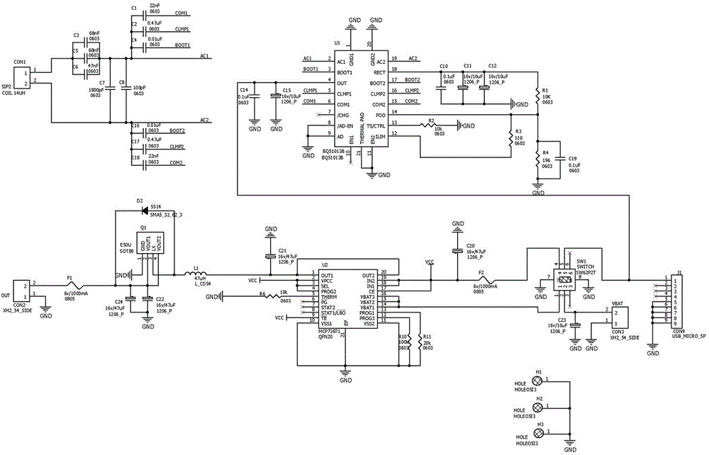
[0050] Among them, the power supply unit includes a wireless charging receiving module, a battery charging management module, a USB power supply module and a receiving electric coil, wherein the wireless charging receiving module...

Embodiment 2

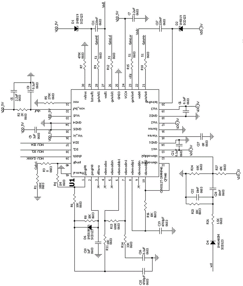
[0124] See figure 2 , figure 2 It is a wireless charging transmitting device in the present invention, and it is matched and matched with the portable smart touch panel with wireless charging function in the first embodiment above.

[0125] Such as figure 2 As shown, the wireless charging transmitting device disclosed in this embodiment specifically includes: a transmitting MCU control unit, a wireless transmitting modulation unit, a dual operational amplifier unit, a dual MOS drive unit, and a transmitting coil.

[0126] The connection relationship of the above modules is as follows: the transmitting coil is connected with the dual MOS driving unit, the dual MOS driving unit is respectively connected with the transmitting MCU control unit and the dual operational amplification unit, and the transmitting MCU control unit is connected with the wireless transmitting modulation unit.

[0127] Wherein, the transmitting MCU control unit is used for the management of wireless c...


PUM


Abstract

The invention discloses a portable intelligent touch panel with a wireless charging function and a wireless charging emission device. The wireless charging function is achieved by using the portable intelligent touch panel and the wireless charging emission device in a matching way. The portable intelligent touch panel comprises a power unit, a touch sensitive unit, a microcontroller unit (MCU) control unit, a wireless emission modulation unit, a dual-operational amplification unit, a dual-metal oxide semiconductor (MOS) driving unit and an emission coil. The touch panel is used for transmitting a signal to the MCU control unit by sensing the capacitance change of an integrated circuit (IC) and a peripheral circuit detection sensitive point, the MCU control unit is used for sending a corresponding command to a wireless fidelity (Wifi) wireless unit after detecting the signal, the Wifi wireless unit is used for sending the signal to achieve wireless control, meanwhile, the power unit is used for supplying power to the whole system, the power is supplied to the whole system held at a hand by a battery, and the wireless charging function is also supported when the whole system is used at the hand.

Description

technical field [0001] The invention relates to the technical field of smart touch panels, in particular to a portable smart touch panel with a wireless charging function and a wireless charging transmitting device thereof. Background technique [0002] In traditional home life, the control of lighting and household appliances is mainly realized by switches. It can be said that the birth of traditional key-type mechanical switches has played an indispensable role in traditional home life. However, because the traditional button-type mechanical switch is difficult to meet the needs of the majority of users, and there has been no qualitative change, it still cannot get rid of the mechanical contact, and the appearance is not novel, and it cannot keep up with the requirements of modern smart homes. [0003] One switch to control one light has become a thing of the past, and traditional switches can no longer meet people's needs in many ways. For example: the traditional switc...

Claims


Application Information

Patent Timeline
IPC IPC(8): H02J7/02H02J50/20
Inventor 余从刚伍永乐曾蔚程
Owner 广东云控照明信息科技有限公司
Why Eureka
Try Eureka