Dynamic igbt gate drive for vehicle traction inverters

A gate driver, inverter technology, applied in the direction of traction, control drive, vehicle components, etc. driven by the engine, which can solve the problems of high current and high voltage of the traction motor.

Active Publication Date: 2016-04-13
FORD GLOBAL TECH LLC
View PDF7 Cites 26 Cited by
  • Summary
  • Abstract
  • Description
  • Claims
  • Application Information

AI Technical Summary

Problems solved by technology

Traction motors may require high voltage and current

Method used

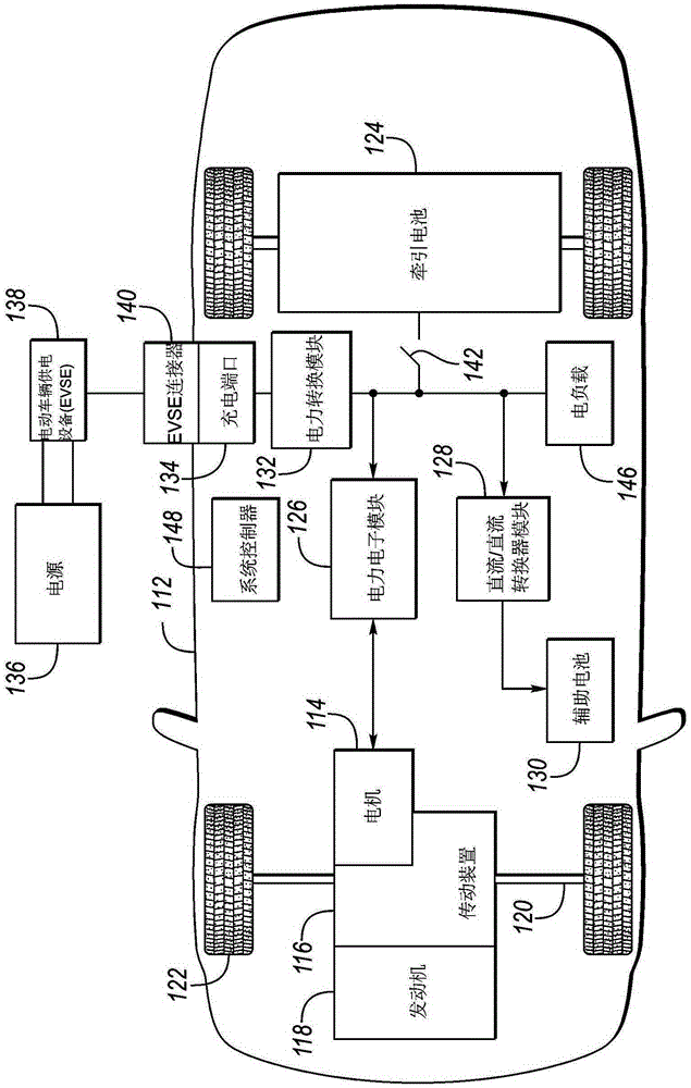
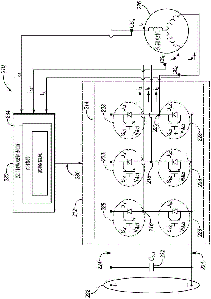
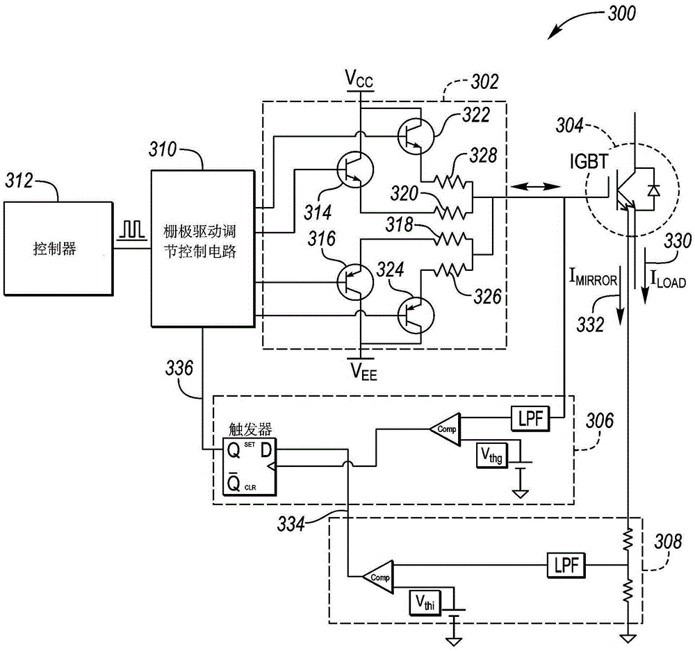

Image

  • Dynamic igbt gate drive for vehicle traction inverters
  • Dynamic igbt gate drive for vehicle traction inverters
  • Dynamic igbt gate drive for vehicle traction inverters

Examples


Embodiment Construction

[0023] Embodiments of the disclosure are described herein. It is to be understood, however, that the disclosed embodiments are merely examples and that other embodiments may be embodied in various and alternative forms. The figures are not necessarily to scale; some features may be exaggerated or minimized to show details of particular components. Therefore, specific structural and functional details disclosed herein are not to be interpreted as limiting, but merely as a representative basis for teaching one skilled in the art to variously employ the present invention. Those skilled in the art will appreciate that various features illustrated and described with reference to any one figure may be combined with features illustrated in one or more other figures to form embodiments not explicitly illustrated or described. The combination of features described provides a representative embodiment for a typical application. However, various combinations and modifications of the fe...


PUM


Abstract

A hybrid electric vehicle includes a traction battery, traction motor and power inverter therebetween. The power inverter converts the DC power of the traction battery to AC power to drive each phase of the traction motor. The power inverter includes Insulated Gate Bipolar junction Transistors (IGBTs) to modulate the power to the traction motor. The speed at which the IGBTs are modulated impacts the system performance including power loss, voltage overshoot and current overshoot. Using a dual emitter IGBT to provide a current mirror of the drive current, circuitry may be used with the gate drive circuitry such that the gate drive speed may be dynamically adjusted based on characteristics including temperature and traction motor rotational speed.

Description

technical field [0001] The present invention generally relates to controlling IGBTs in traction inverters based on characteristics including mirror current, IGBT temperature and traction motor speed. Background technique [0002] Hybrid electric vehicles and pure electric vehicles rely on the traction battery to provide power to the traction motor for propulsion and the power inverter in between that converts the battery DC (direct current) power to AC (alternating current) power for the traction motor. A typical AC traction motor is a three-phase motor that can be driven by three sinusoidal signals each driven by 120-degree phase separation. Traction motors can require high voltages and high currents. Insulated gate bipolar transistors (IGBTs) are commonly used to generate signals in power inverters due to voltage, current and switching requirements. Contents of the invention [0003] An inverter controller includes: a dual-emitter IGBT having a gate, a first emitter, a...

Claims


Application Information

Patent Timeline
Patent Type & Authority Applications(China)
IPC IPC(8): H02M1/08H02M7/5387H02P27/06H02M1/00H02M1/32
CPCB60L1/003B60L1/02B60L15/007B60L2210/10B60L2210/30B60L2210/40B60L2240/12B60L2240/34B60L2240/36B60L2240/421B60L2240/423B60L2240/425B60L2240/441B60L2240/443B60L2240/547B60L2240/549B60L50/16B60L50/61B60L50/66B60L53/14B60L58/20H02M1/08H02M7/53871H03K17/14H02P29/68H02M1/0009H02M1/327Y02T10/62Y02T10/64Y02T10/70Y02T10/7072Y02T10/72Y02T90/14Y02T90/12
Inventor 陈礼华曹东沙雷斯·斯坎特·柯扎雷卡尔沙赫拉姆·萨雷吴宏杰唐宇清
Owner FORD GLOBAL TECH LLC
Why Eureka
Try Eureka