Bearing oil-coating device

An oiling device and bearing technology, which is applied in the fields of bearing processing equipment and bearing oiling devices, can solve the problems of high labor intensity, low efficiency, waste of lubricating oil, etc., and achieve simple equipment structure, low investment cost, and saving lubricating oil Effect

Active Publication Date: 2016-04-20
新昌县林泉轴承有限公司
View PDF5 Cites 22 Cited by
  • Summary
  • Abstract
  • Description
  • Claims
  • Application Information

AI Technical Summary

Problems solved by technology

[0002] After the bearing is processed and assembled, lubricating oil will be applied between the inner ring and the outer ring of the bearing before packaging. The purpose is to prevent the bearing from rusting during storage, and it is also convenient for users to apply immediately. The oil nozzle sprays oil between the inner ring and the outer ring, and achieves the purpose of fuel saving through the method of precise oil injection. After the oil is applied and rotated, some excess oil will overflow, so the bearing often needs to be correspondingly oiled after oiling. The equipment wipes off the excess oil, which not only wastes the lubricating oil, but also increases the investment cost of the equipment, and each time the bearings are oiled one by one, which is inefficient and labor-intensive. At present, some oiling machines only One type of bearing can be painted, but the usability is greatly limited, and the economy is very poor

Method used


Image

  • Bearing oil-coating device
  • Bearing oil-coating device
  • Bearing oil-coating device

Examples


Embodiment Construction

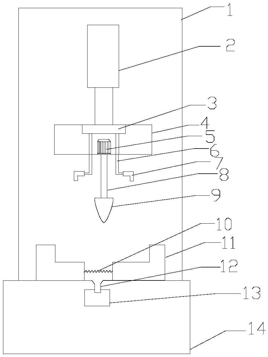
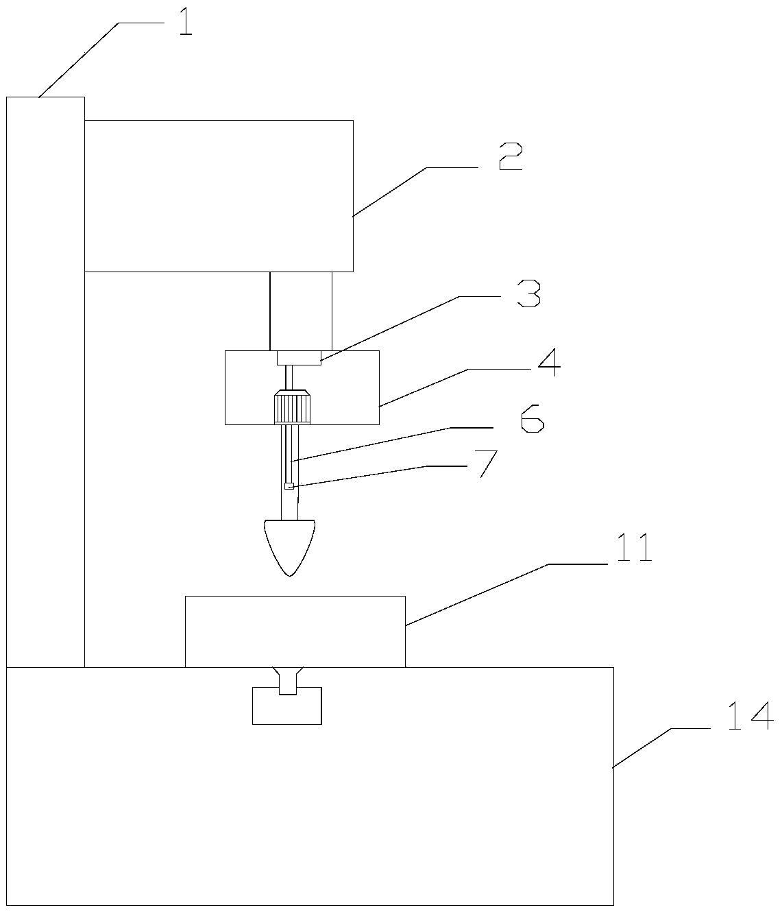
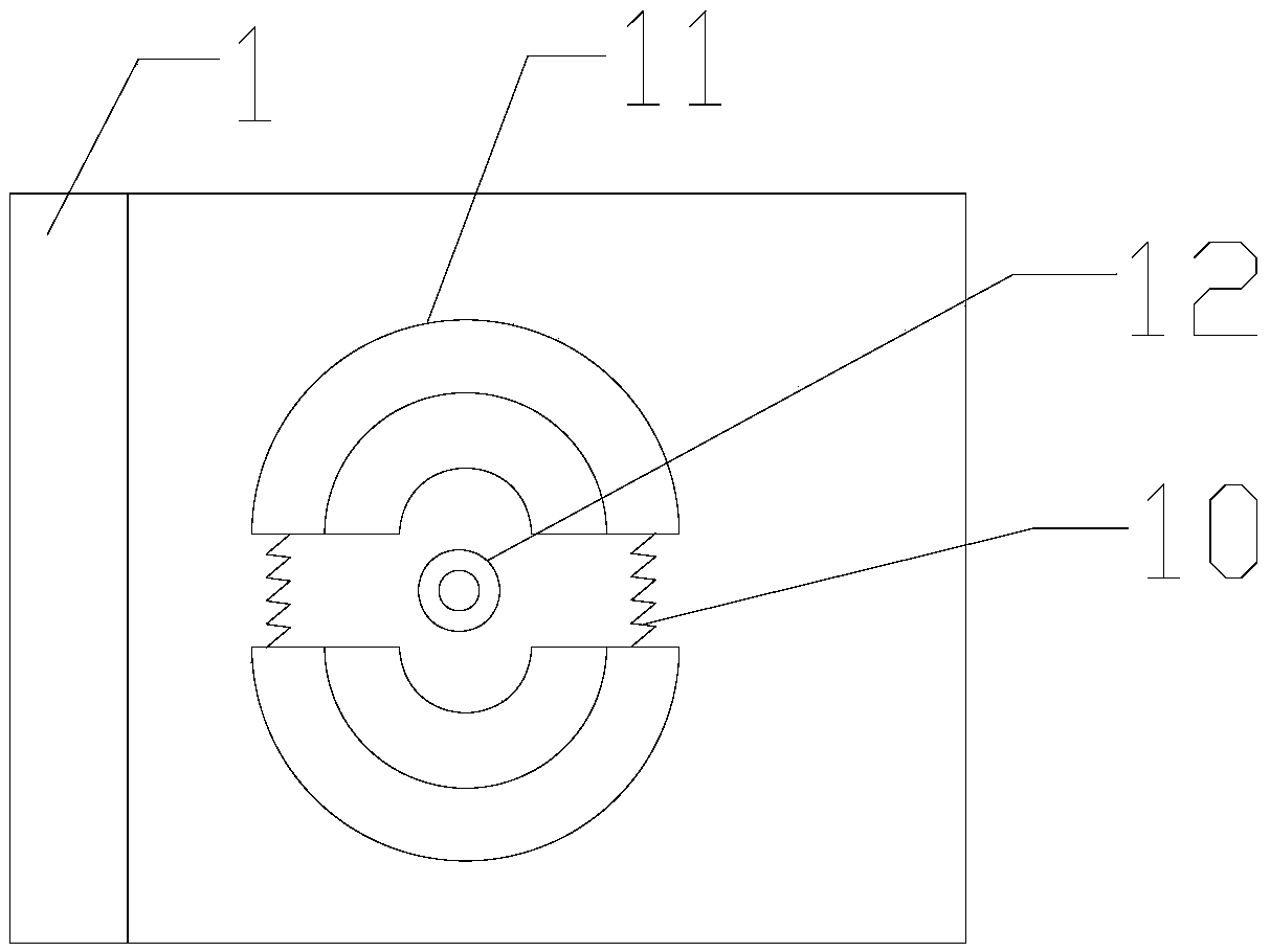
[0014] refer to figure 1 , figure 2 with image 3 , a bearing oiling device of the present invention, comprising a machine platform 14, a fixed bracket 1, a hydraulic cylinder 2, a fixed cover 4, an oil injection pump 3, a spray pipe 6, an atomized oil nozzle 7, a rotating motor 5, a rotating shaft 8, Tensioning rotary head 9, fixed block 11, described fixed support 1 is vertically fixed on the side top of machine platform 14, and described fixed support 1 top is fixed with hydraulic cylinder 2, and described hydraulic cylinder 2 bottom is connected with fixed cover 4, The fuel injection pump 3 and the rotating motor 5 are installed in the fixed cover 4, the fuel injection pump 3 is connected with a spray pipe 6, the spray pipe 6 protrudes from the bottom of the fixed cover 4, and the atomized oil nozzle 7 is installed At the end of the spray pipe 6, the rotating motor 5 is fixed on the bottom of the fixed cover 4, the bottom of the rotating motor 5 is connected with a rota...


PUM


Abstract

The invention discloses a bearing oil-coating device. The bearing oil-coating device comprises a platform, a fixing support, a hydraulic cylinder, a fixing cover, an oil injection pump, spray pipes, atomized oil spray heads, a rotation motor, a rotation shaft, a tensioning swivel and fixing blocks, wherein the fixing support is vertically fixed at the top of the side surface of the platform; the hydraulic cylinder is fixed at the top of the fixing support; the fixing cover is connected to the lower part of the hydraulic cylinder; the oil fuel injection pump and the rotation motor are installed in the fixing cover; the spray pipes are connected to the oil fuel injection pump; the atomized oil spray heads are installed at the tail ends of the spray pipes; the rotation shaft is connected to the lower part of the rotation motor; the tensioning swivel is installed at the lower end of the rotation shaft; the fixing blocks are installed at the top of the platform; and a waste oil recovery hole is formed in the top of the platform. According to the invention, bearing oil-coating can be automatically carried out, lubricant oil can be saved, the oil-coating efficiency is high, and the oil-coating is uniform; and the equipment is simple in structure, low in investment cost and capable of coating different types of bearings.

Description

【Technical field】 [0001] The invention relates to the technical field of bearing processing equipment, in particular to the technical field of a bearing oiling device. 【Background technique】 [0002] After the bearing is processed and assembled, lubricating oil will be applied between the inner ring and the outer ring of the bearing before packaging. The purpose is to prevent the bearing from rusting during storage, and it is also convenient for users to apply immediately. The oil nozzle sprays oil between the inner ring and the outer ring, and achieves the purpose of fuel saving through the method of precise oil injection. After the oil is applied and rotated, some excess oil will overflow, so the bearing often needs to be correspondingly oiled after oiling. The equipment wipes off the excess oil, which not only wastes the lubricating oil, but also increases the investment cost of the equipment, and each time the bearings are oiled one by one, which is inefficient and labor...

Claims


Application Information

Patent Timeline
Patent Type & Authority Applications(China)
IPC IPC(8): B05B13/02B05B9/04B05B15/04
CPCB05B9/04B05B9/0403B05B12/16B05B13/02Y02P70/10
Inventor 俞玉兰
Owner 新昌县林泉轴承有限公司
Why Eureka
Try Eureka