Steel bar straightening and shearing machine and steel bar straightening and shearing method

A technology of cutting machine and cutting mechanism, which is applied in the field of steel bar straightening and cutting machine and steel bar straightening and cutting, and can solve the problems of poor quality of welded mesh, bending of steel bar ends, slow falling speed, etc.

Active Publication Date: 2016-04-20
安志攀
View PDF7 Cites 2 Cited by
  • Summary
  • Abstract
  • Description
  • Claims
  • Application Information

AI Technical Summary

Problems solved by technology

The currently used straightening and cutting machine has the following defects due to structural reasons: first, the steel bar channel behind the cutter is fixed, and during the cutting process of the cutter, it is easy to cause the end of the steel bar to bend, making the quality of the welded mesh poor; second, In order to avoid the bending of the steel bar, the lower end of the steel bar channel should be as close as possible to the cutter, resulting in incomplete cutting of the steel bar, which will easily cause damage to the cutter and reduce the service life of the cutter; Falling along the blanking slant, corresponding to the thick steel bars with larger diameters, the steel bars can fall quickly, but for the thin steel bars with smaller diameters, the falling speed is slow, resulting in the steel bars not falling quickly, and the work efficiency is greatly reduced

Method used


Image

  • Steel bar straightening and shearing machine and steel bar straightening and shearing method
  • Steel bar straightening and shearing machine and steel bar straightening and shearing method
  • Steel bar straightening and shearing machine and steel bar straightening and shearing method

Examples


Embodiment Construction

[0043] The structure and operating principle of the steel bar straightening and cutting machine of the present invention will be further described in detail below in conjunction with the accompanying drawings and specific embodiments.

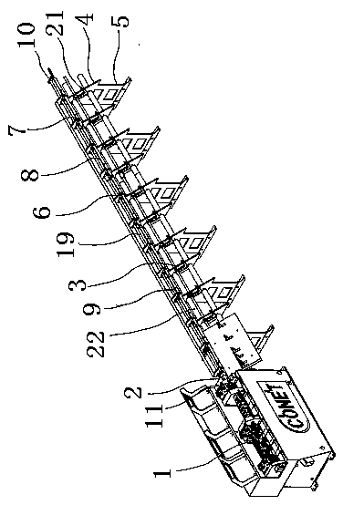
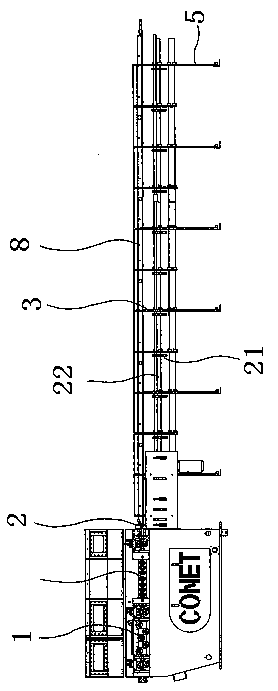
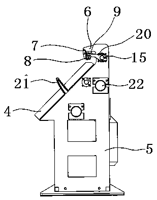
[0044] Such as figure 1 , figure 2 with image 3As shown, the structure diagram of the steel bar straightening and cutting machine of the present invention, the steel bar straightening and cutting machine of the present invention includes a straightening mechanism 1, a cutting mechanism 2 and a discharge mechanism 3, and the discharge mechanism 3 includes a frame with a blanking ramp 4 Body 5, an inverted "L"-shaped hook 6 is arranged above the frame body 5, and an "L"-shaped angle steel 8 is connected to an "L"-shaped angle steel 8 near the front lower end of the suspension hook 6 through a movable chain flap 7, and the vertical edge 81 of the angle steel 8 It is movably connected with the movable chain flap 7, and a channel steel 9 with an...


PUM


Abstract

The invention belongs to the technical field of a steel bar straightening and shearing machine and a steel bar straightening and shearing method and discloses the steel bar straightening and shearing machine and the steel bar straightening and shearing method. The steel bar straightening and shearing machine and the steel bar straightening and shearing method are mainly technically characterized in that an unloading mechanism comprises frame bodies with discharging inclined plates, lifting hooks are arranged above the frame bodies, the lower ends of the lifting hooks are connected to angle iron through movable chain flaps, and box iron with an opening at the lower end is arranged above a horizontal side of each piece of angle iron; a cutting mechanism comprises a fixing frame, a lower cutter fixed to the lower part, an upper cutter fixing base and an upper cutter located on the upper cutter fixing base, a first rotating shaft is fixed to the fixing frame through a bearing, the upper cutter fixing base is connected to the first rotating shaft through a shaft pin, one end of the first rotating shaft is fixedly connected to the end of the box iron, a swing rod is arranged at the other end of the first rotating shaft, a second rotating shaft is arranged on a frame body and is provided with a rotating connection rod synchronous with the second rotating shaft, the front end of the rotating connection rod is fixedly connected to the upper end of the box iron, and the box iron is movably provided with a connecting plate. According to the invention, the falling speed is increased, and the production efficiency is further improved.

Description

technical field [0001] The invention belongs to the technical field of steel bar straightening and cutting machines, in particular to a steel bar straightening and cutting machine and a method for straightening and cutting steel bars. Background technique [0002] For the convenience of storage and transportation, the steel bars used to weld the mesh are generally in the form of rolls. Before welding the mesh, the steel bars need to be straightened and cut according to a certain length, and the straightened and cut steel bars are temporarily stored in the storage tank. The currently used straightening and cutting machine has the following defects due to structural reasons: first, the steel bar channel behind the cutter is fixed, and during the cutting process of the cutter, it is easy to cause the end of the steel bar to bend, making the quality of the welded mesh poor; second, In order to avoid the bending of the steel bar, the lower end of the steel bar channel should be ...

Claims


Application Information

Patent Timeline
Patent Type & Authority Applications(China)
IPC IPC(8): B21F1/02B21F11/00
CPCB21F1/026
Inventor 安志攀
Owner 安志攀
Why Eureka
Try Eureka