
A drilling machine positioning claw

A drilling machine and claw technology, applied in positioning devices, metal processing machinery parts, clamping, etc., can solve the problems of complex processing technology, low processing accuracy, low production efficiency, etc., and achieve improved positioning efficiency and pressure-bearing Good effect and well-structured effect

Active Publication Date: 2017-12-19
ZHENJIANG YUJIU INTELLIGENT EQUIP LTD BY SHARE LTD
View PDF10 Cites 0 Cited by
  • Summary
  • Abstract
  • Description
  • Claims
  • Application Information

AI Technical Summary

Problems solved by technology

There are still many defects in the production process and production equipment of the wheel hub. For example, the intermediate shaft hole of the traditional aluminum wheel hub is manually controlled, and the hole is tapped by a drilling machine. The processing technology is complicated, the processing accuracy is not high, and the production efficiency is low. ; Moreover, for machining holes on the hub, the drill bit is usually drilled one by one, and manual calibration is required after positioning one by one, which is inaccurate and time-consuming.

Method used


Image

  • A drilling machine positioning claw
  • A drilling machine positioning claw
  • A drilling machine positioning claw

Examples


Embodiment

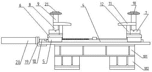
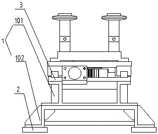
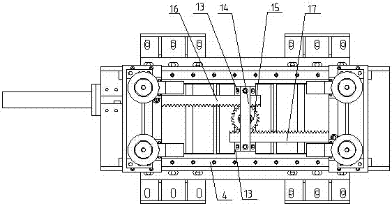
[0018] A positioning jaw of a drilling machine, including a jaw support frame 1, the jaw support frame 1 includes a first support frame 101 and a second support frame 102, and the bottom sides of the first support frame 101 are provided with multiple Bolt holes, the cross-section of the second support frame 102 is an "n"-shaped structure, the top of the second support frame 102 is provided with a plurality of bolt holes, and the bottom two sides are provided with a plurality of bolt holes, through which the first support frame Bolt holes at the bottom of 101 and bolt holes at the top of the second support frame 102 realize the bolt connection between the first support frame 101 and the second support frame 102; the bottom of the second support frame 102 is fixedly connected with a support connecting plate 2; The plate 2 is fixed on the bottom plate of the drilling machine frame; the top of the first support frame 101 is connected with a track plate 3, and the track plate 3 is p...


PUM


Abstract

The invention discloses a positioning clamping jaw of a drilling machine. The positioning clamping jaw comprises a clamping jaw support frame; the clamping jaw support frame includes a first support frame and a second support frame; the bottom of the second support frame is connected with a bracket connecting plate; the top of the first support frame is connected with a rail plate; a rail is arranged on the rail plate; slide blocks are arranged at two ends of the slide, and are provided with slide plates; clamping jaw bases are arranged on the slide plates; two clamping rods are arranged on the clamping jaw bases; shaft sleeves are arranged out of the clamping rods; clamping wheels are arranged at the tops of the clamping rods; clamping jaw stoppers are arranged in the middle positions of the clamping rods; stopper support blocks are arranged at the bottoms of the clamping jaw stoppers; fixed stoppers are arranged on the rail plate; the tops of the two fixed stoppers are connected with fixed transverse plates; gears are arranged at the bottoms of the fixed transverse plates; the bottoms of the two slide plates are connected with driving racks and driven racks; the driving racks are connected with an oil cylinder; the oil cylinder is fixed at one end of the rail plate; and the driving racks and the driven racks are both engaged to the gears. The positioning clamping jaw mechanism is designed to realize mechanical positioning without needing manual calibration, realizes automatic production, and is high in efficiency and precise in positioning.

Description

technical field [0001] The invention relates to a drilling machine, in particular to a drilling machine positioning claw. Background technique [0002] The wheel hub is also called the rim, the wheel, and the tire bell. It is a barrel-shaped, center-mounted metal part that supports the tire on the inner profile of the tire. There are still many defects in the production process and production equipment of the wheel hub. For example, the intermediate shaft hole of the traditional aluminum wheel hub is manually controlled, and the hole is tapped by a drilling machine. The processing technology is complicated, the processing accuracy is not high, and the production efficiency is low. ; And for processing holes on the wheel hub, generally drill bits drill holes one by one, and need to manually calibrate after positioning one by one, the positioning is inaccurate and time-consuming and laborious. Contents of the invention [0003] In order to overcome the defects of the prior ...

Claims


Application Information

Patent Timeline
Patent Type & Authority Patents(China)
IPC IPC(8): B23Q3/00
CPCB23Q3/00B23Q2703/04
Inventor 肖双喜张苏嵘
Owner ZHENJIANG YUJIU INTELLIGENT EQUIP LTD BY SHARE LTD
Learn More