Machining method for abrasive flow deburring of bushing-like components
A processing method and burr technology, applied in the field of mechanical processing technology, can solve the problems of difficult to observe the burr of the cross hole in the inner cavity, the burr is not clean, and the performance stability of the valve is affected, so as to achieve the improvement of the pass rate, the surface roughness and the cylindrical shape The effect of improved degree and stable quality
- Summary
- Abstract
- Description
- Claims
- Application Information
AI Technical Summary
Problems solved by technology
Method used
Image
Examples
Embodiment 1
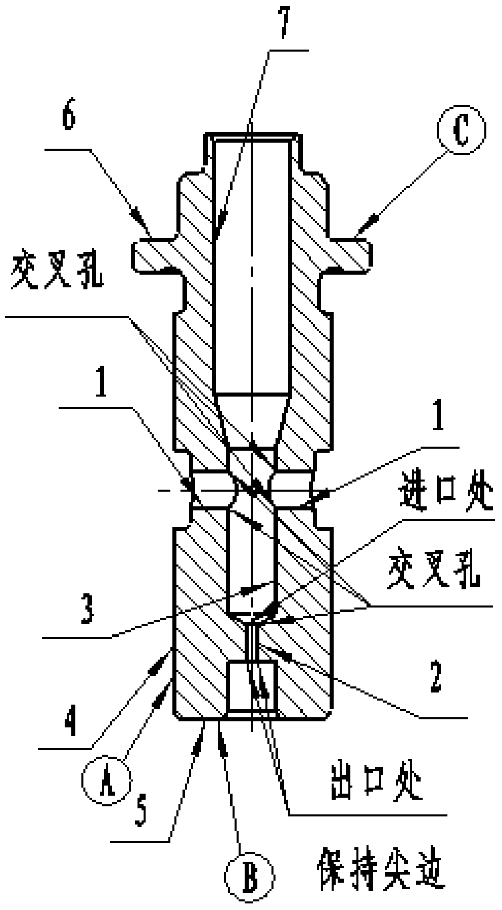
[0018] This embodiment provides a processing method for abrasive flow deburring of bushing parts, which is characterized in that: the processing method for abrasive flow deburring of bushing parts, the abrasive flow deburring process of the inner cavity of the bushing Such as figure 1 As shown, there are 2 radial holes 1 of φ2 in the inner cavity, and 1 small hole 2 of φ0.6 in the axial direction, and the outlet of the small hole 2 keeps a sharp edge, 2 radial holes 1 and 1 oil inlet hole 3 There is no special requirement for the intersection, and it is processed according to the grinding sharp edge R0.1~0.3mm, and the surface roughness is Ra3.2.
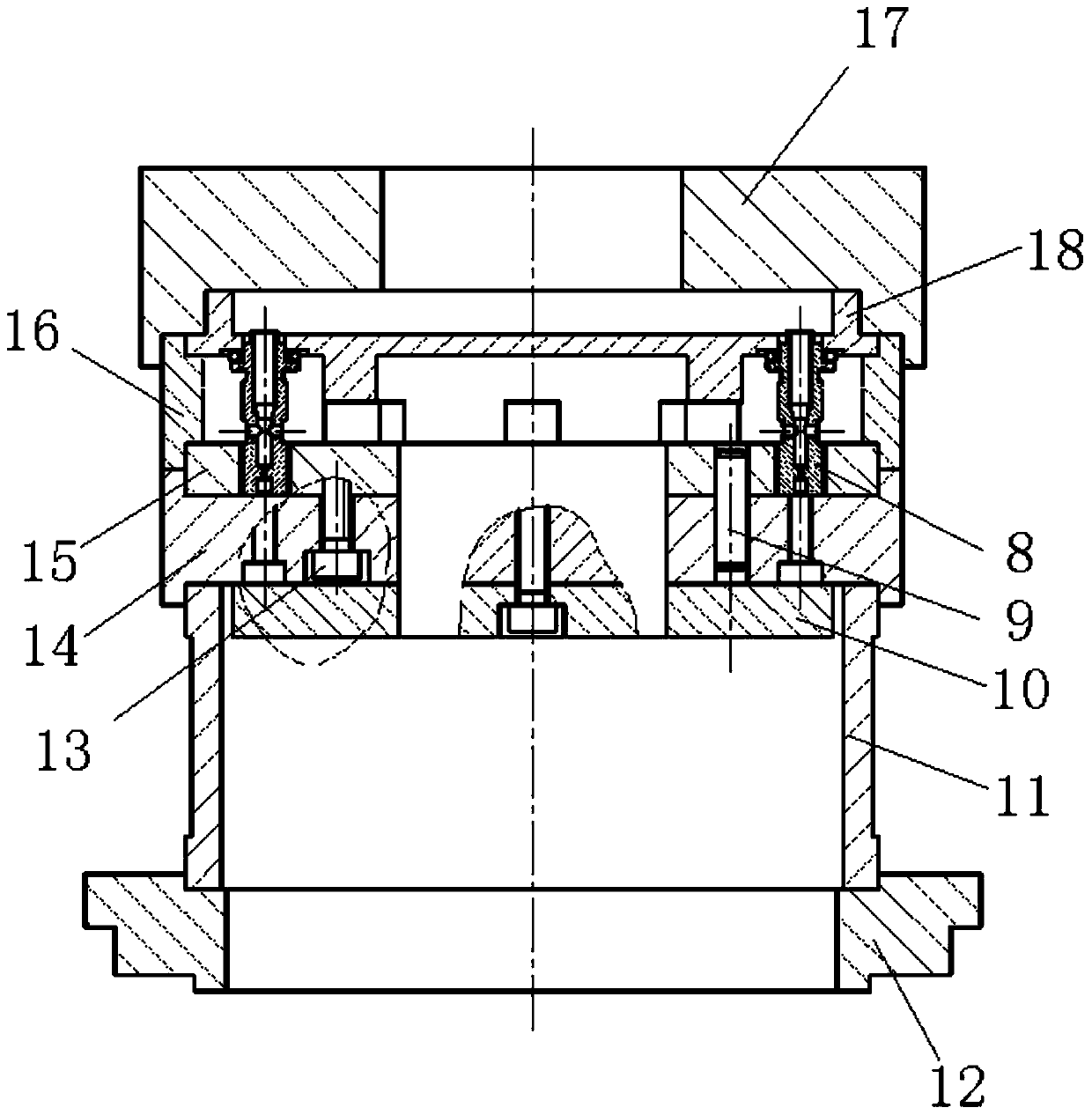
[0019] In order to eliminate the burrs at the intersection of the radial hole 1 and the oil inlet hole 3, as well as the small hole 2 and the oil inlet hole 3, a set of special fixtures is designed, and the abrasive flow abrasive MF17-150S (75) imported from Germany is used;
[0020] outer circle and end faces Locate and press ...
Embodiment 2
[0024] This embodiment provides a processing method for abrasive flow deburring of bushing parts, which is characterized in that: the processing method for abrasive flow deburring of bushing parts, the abrasive flow deburring process of the inner cavity of the bushing Such as figure 1 As shown, there are 2 radial holes 1 of φ2 in the inner cavity, and 1 small hole 2 of φ0.6 in the axial direction, and the outlet of the small hole 2 keeps a sharp edge, 2 radial holes 1 and 1 oil inlet hole 3 There is no special requirement for the intersection, and it is processed according to the grinding sharp edge R0.1~0.3mm, and the surface roughness is Ra3.2.
[0025] In order to eliminate the burrs at the intersection of the radial hole 1 and the oil inlet hole 3 and the small hole 2 and the oil inlet hole 3, a set of special fixtures is designed, and the abrasive flow abrasive MF17-100S (100) imported from Germany is used.
[0026] outer circle and end faces Locate and press the upp...
Embodiment 3
[0030] This embodiment provides a processing method for abrasive flow deburring of bushing parts, which is characterized in that: the processing method for abrasive flow deburring of bushing parts, the abrasive flow deburring process of the inner cavity of the bushing Such as figure 1 As shown, there are 2 radial holes 1 of φ2 in the inner cavity, and 1 small hole 2 of φ0.6 in the axial direction, and the outlet of the small hole 2 keeps a sharp edge, 2 radial holes 1 and 1 oil inlet hole 3 There is no special requirement for the intersection, and it is processed according to the grinding sharp edge R0.1~0.3mm, and the surface roughness is Ra3.2.
[0031] In order to eliminate the burrs at the intersection of the radial hole 1 and the oil inlet hole 3 and the small hole 2 and the oil inlet hole 3, a set of special fixtures was designed, using German imported abrasive flow abrasives MF17-100S (100), MF17-150S (75 ) and MF17-220S (75);
[0032] outer circle and end faces L...
PUM
 Abstract
Description
Claims
Application Information
 - R&D
- Intellectual Property
- Life Sciences
- Materials
- Tech Scout
- Unparalleled Data Quality
- Higher Quality Content
- 60% Fewer Hallucinations
Browse by: Latest US Patents, China's latest patents, Technical Efficacy Thesaurus, Application Domain, Technology Topic, Popular Technical Reports.
© 2025 PatSnap. All rights reserved.Legal|Privacy policy|Modern Slavery Act Transparency Statement|Sitemap|About US| Contact US: help@patsnap.com


