Static railway track assembly overall dimension and damage optical detection system

A technology of optical detection and railway track, which is applied in the direction of track, track maintenance, track superstructure, etc., and can solve the problems of low detection efficiency and low detection efficiency

Active Publication Date: 2016-04-20
李社军
View PDF5 Cites 10 Cited by
  • Summary
  • Abstract
  • Description
  • Claims
  • Application Information

AI Technical Summary

Problems solved by technology

When using the rail bottom slope measuring instrument installed with an inclination sensor inside to detect the slope of the bottom surface of the rail, first place the sleeper slope detection reference plane of the rail bottom slope measuring instrument on the sleeper, measure the horizontal inclination of the sleeper, and then place the The rail bottom slope detection reference plane of the bottom slope measuring instrument is stuck on the rail bottom surface of the rail, and the horizontal inclination angle of the bottom of the current rail is measured. The difference between the two angle values ​​is the current rail bottom slope value of the rail. The measurement of the slope of the rail bottom requires three measurements of the inclination angle and two calculations to obtain it. One measurement takes no less than 60 seconds, and the detection efficiency is low
[0006] At present, the detection of the loosening or falling off of the rail fastener combination nut caused by the vibration of the train, as well as the cracks and falling blocks of the concrete sleeper and ballastless track sleeper board are carried out by manual visual inspection and manual recording. The detection efficiency low, needs improvement

Method used


Image

  • Static railway track assembly overall dimension and damage optical detection system
  • Static railway track assembly overall dimension and damage optical detection system
  • Static railway track assembly overall dimension and damage optical detection system

Examples


Embodiment 1

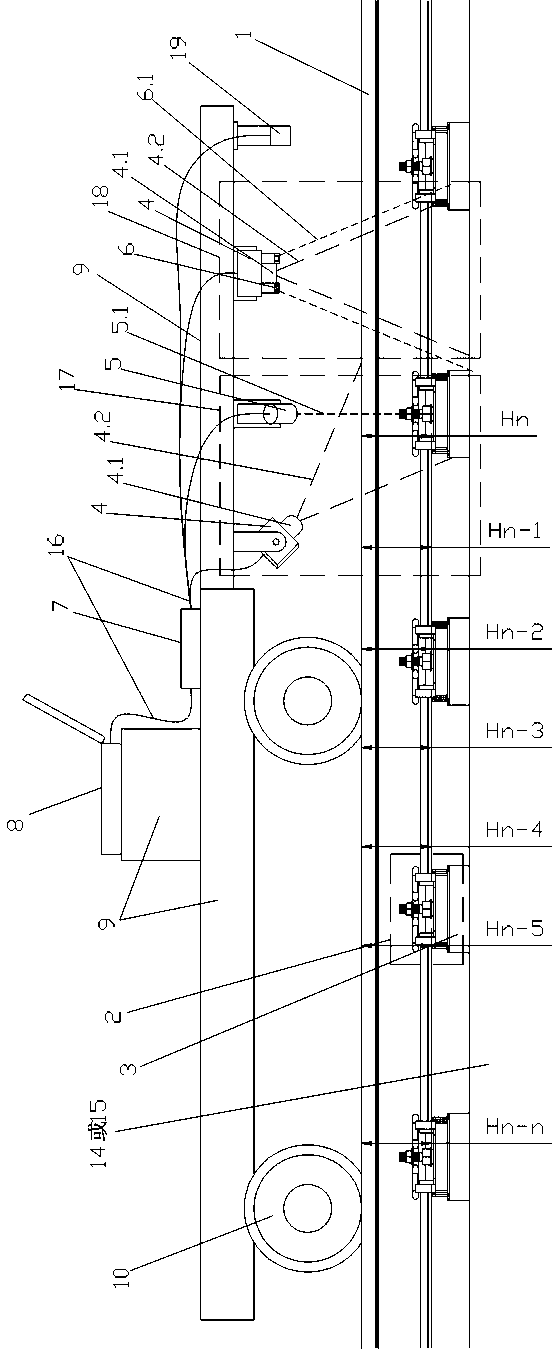
[0065] see figure 1 , a static railway track component outline dimension and optical detection system for disease, this system is used for the detection of static railway track component and track disease, the system includes rail and rail fastener combined contour section size optical detection sub-system 17, track disease Optical detection sub-system 18, image processing card 8, computer (or notebook computer or palmtop computer) 9, data, power supply cable 16 and walking type mechanical frame 9, mileage sensor 10, distance sensor 19 composition, also can rail and rail The optical detection sub-system 17 of the profile and section size of the fastener assembly or the optical detection sub-system 18 of the track defect is separately installed on the walking mechanical frame 9 and the image processing card 8, computer (or notebook computer or palmtop computer) 9, data and power cables 16. The distance sensors 19 are connected to realize corresponding detection functions.

Embodiment 2

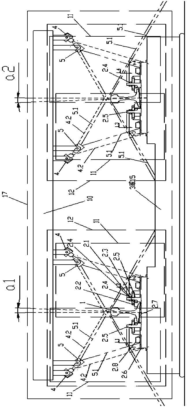
[0067] see figure 2 An optical detection sub-system 17 for the outline size and defect optical detection system of a static railway track component outline size and rail fastener combined outline section size 17, including a high-speed camera 4, an inline strong light source 5, an image processing card 8, and a computer ( Or notebook computer or palmtop computer) 9, data, power supply cable 16, walking type mechanical frame 9, mileage sensor 10, distance sensor 19, described inline glare light source 5 and high-speed camera 4 are arranged on rail side, so A high-speed camera 4 for optical detection and an in-line strong light source 5 constitute a set of optical detection group 11 for the combined contour section size of rails and rail fasteners. 11 is set at a position higher than the rail surface on the side of the rail 1, and the two sets of rails and rail fasteners on both sides of the same rail 1 are respectively located on the two sides of the same rail 1. The optical d...

Embodiment 3

[0078] The high-speed camera 4 for optical detection and a group of ring-shaped strong light sources 6 constitute a set of track defect optical detection unit 13, and the track defect optical detection unit 13 is arranged above the top surface of the rail 1, and the optical detection uses high-speed Camera 4 is connected with image processing card 8 and computer (or notebook computer or palmtop computer) 9 via data and power cables 16 . Said, the image collected by the high-speed camera 4 is transmitted to the image processing card 8 through the data and the power cable 16, and then transmitted to the computer (or notebook computer or palmtop computer) 9 after the sharpening of the image boundary and the calculation of the optical center of gravity, After the image information is processed by the computer (or notebook computer or palmtop computer) 9, the information and images of the local wear on the top surface of the rail, the falling block 1.7 and the rail crack 3.4 are obt...


PUM


Abstract

The invention provides a static railway track assembly overall dimension and damage optical detection system which comprises linear hard light sources, annular hard light sources, high-speed cameras for optical detection, an image processing card, a computer, data and power source cables, walking type machine frameworks and mileage sensors installed on wheels of the walking type machine frameworks. A track assembly comprises steel rails, steel rail fastener combinations, sleepers, sleeper plates and railway ballasts. Each high-speed camera for optical detection and the corresponding linear hard light source which are installed on the corresponding walking type machine framework and located on the same side of the same corresponding steel rail and are higher than the rail surface form a steel rail and steel rail fastener combination contour section dimension optical detecting set. By means of the technology, the functions of detecting the steel rail overall dimension, the steel rail top face corrugated abrasion and rail bottom slopes and the functions of detecting steel rail fastener gland nut loosening, failures and missing are achieved.

Description

technical field [0001] The present invention relates to a kind of optical detection system for outline size and disease of static railway track components, more precisely, it is an optical system for comprehensively detecting the state of railway track components in a static state where the applied load cannot deform them. Detection Systems. As opposed to static railway inspections, dynamic inspections such as passenger and freight trains, rail cars, and track inspection vehicles are loaded on the railway tracks, which are sufficient to deform railway track components. Background technique [0002] On the running railway, whether it is due to the wheel idling caused by the emergency acceleration of the running train, or the wheel lock caused by the emergency braking deceleration, which aggravates the wavy wear and block on the top surface of the rail, or the rail head caused by normal operation The abnormal wear or broken rail of the rail head caused by wavy wear, fat edge ...

Claims


Application Information

Patent Timeline
Patent Type & Authority Applications(China)
IPC IPC(8): E01B35/12
CPCE01B35/12E01B2203/16
Inventor 唐树生李社军
Owner 李社军
Why Eureka
Try Eureka