Inner sleeve constraint folding steel plate energy dissipation support

An energy-dissipating support and inner casing technology, which is applied to building components, shock-proof and other directions, can solve the problems that the energy-dissipation performance of the support cannot be accurately controlled, the position of the yield point of the core board cannot be controlled, and the energy-dissipation capacity of the core board cannot be exerted. To achieve the effect of simple structure, preventing buckling under compression, and convenient production

Active Publication Date: 2016-04-20
SOUTHEAST UNIV
View PDF10 Cites 16 Cited by
  • Summary
  • Abstract
  • Description
  • Claims
  • Application Information

AI Technical Summary

Problems solved by technology

[0004] However, there are few plastic hinges in the current buckling-constrained energy-dissipating supports, which cannot exert the energy-dissipating capacity of the entire core plate, cannot control the yield po

Method used


Image

  • Inner sleeve constraint folding steel plate energy dissipation support
  • Inner sleeve constraint folding steel plate energy dissipation support
  • Inner sleeve constraint folding steel plate energy dissipation support

Examples


Embodiment 1

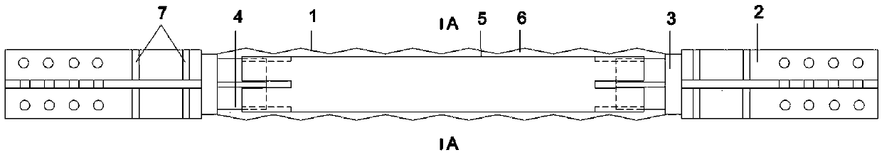
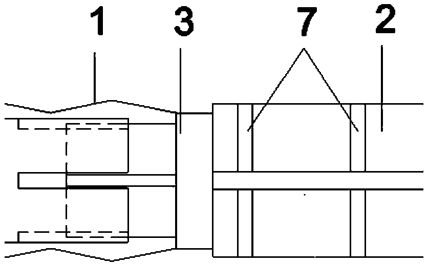
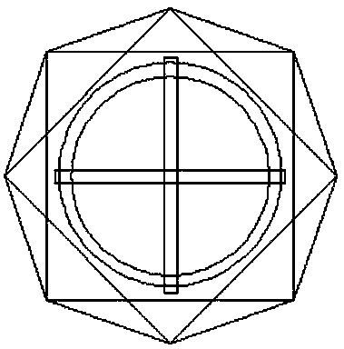
[0036] like Figure 1 to Figure 5 Shown, the present invention is made up of core tube 1, cross gusset plate 2, end bearing plate 3, cross fixing plate 4, inner casing 5, non-adhesive material 6, and stiffener 7 seven parts. The core barrel 1 is formed by punching steel plates into different simple geometric figures, and then welded to form a cylindrical shape. As shown in FIG. 4 , in this embodiment, the geometric figure on the core barrel 1 is a combination of isosceles triangles. It is folded like Figure 5 As shown, it is the crease pattern in this embodiment, the two ends are welded to form the core tube 1, and the dotted line is the dent. like figure 2 As shown, the end pressure plate 3 is connected to the core barrel 1, and the end pressure plate 3 is welded to the four sides of the mouth of the core barrel 1, and the size of the end pressure plate 3 is the same as that of the mouth of the core barrel 1. At the same time, the cross fixing plate 4 is welded on the i...

Embodiment 2

[0038] This embodiment is the same as the rest of Embodiment 1, except that the circular tube of the inner casing 5 is replaced by a square tube to provide constraints.

[0039]In order to express the spatial structure of the subunit more clearly, establish a space Cartesian coordinate system to describe the coordinates of each node, as shown in Figure 8, the coordinate origin O is the center of the subunit, and the straight line where the diagonal FH of the quadrilateral EFGH is located is used as the X axis , from F to H is the positive direction, take the straight line where the other diagonal EG of the quadrilateral is located as the Z-axis, point from E to G as the positive direction, and take the straight line passing through point O and perpendicular to the X-axis and Z-axis as the Y-axis, The positive direction is from the plane ABCD to the plane IJKL.

[0040] The size of the energy dissipation unit should meet the following conditions (θ is the dihedral angle between...


PUM

PropertyMeasurementUnit
Thicknessaaaaaaaaaa

Abstract

The invention discloses an inner sleeve constraint folding steel plate energy dissipation support. The energy dissipation support comprises a core cylinder, an inner sleeve arranged in the core cylinder, end load bearing plates arranged at cylinder openings in the two sides of the core cylinder, a crossed fixed plate arranged in the inner sleeve and connected with the inner sides of the end load bearing plates and a crossed gusset plate connected to the outer sides of the end load bearing plates. The core cylinder is formed by sequentially connecting multiple energy consumption units. Each energy consumption unit consists of 4n triangles with different surfaces. The energy dissipation support produces pre-folding traces through folding steel plates and can produce plastic hinge lines at the folding traces when bearing a load, and the energy consumption capacity of the support is enhanced through the plastic hinge lines; meanwhile, the sleeve is arranged in the core cylinder to improve annular constraint to the core cylinder, and therefore the rigidity and ultimate bearing capacity of the support can be improved conveniently.

Description

technical field [0001] The invention belongs to the field of building structure energy-dissipating supports, and relates to an energy-dissipating support of folded steel plates constrained by inner casings. Background technique [0002] An earthquake is a strong natural disaster, and the energy released during an earthquake can cause fatal damage to buildings. In order to absorb the energy released during an earthquake to protect buildings, avoid damage to buildings caused by excessive energy input, and protect people's lives and property, buckling restraint support devices are widely used. [0003] The buckling restrained brace is mainly composed of core plate, outer casing, unbonded material and other parts. In this technology, the core plate is the main force-bearing unit, and the core plate deforms under the action of an earthquake to consume the energy input by the earthquake, so as to achieve the purpose of protecting the main frame. The inner casing prevents the lat...

Claims


Application Information

Patent Timeline
IPC IPC(8): E04B1/98
CPCE04B1/98
Inventor 陆金钰杨连坤谯旭东
Owner SOUTHEAST UNIV
Why Eureka
Try Eureka