a load template

A formwork and support technology, which is applied to formwork/formwork components, connection parts of formwork/formwork/work frame, and on-site preparation of building components, can solve problems such as the inability of building formwork bearing strength to support temporary model structures. , to achieve the effect of simple structure, improving cycle efficiency and reducing utilization

Active Publication Date: 2019-03-19
NENGCHENG GRP
View PDF11 Cites 0 Cited by
  • Summary
  • Abstract
  • Description
  • Claims
  • Application Information

AI Technical Summary

Problems solved by technology

[0005] For this reason, the technical problem to be solved by the present invention lies in the problem that the temporary model structure built cannot be supported by the bearing strength of the building formwork itself in the prior art, and then provides a load-bearing formwork that can be used as a supporting structure for the temporary model structure

Method used


Image

  • a load template
  • a load template
  • a load template

Examples


Embodiment 1

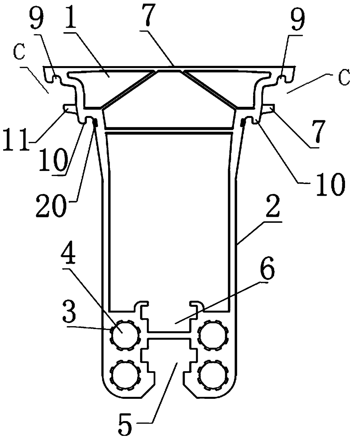
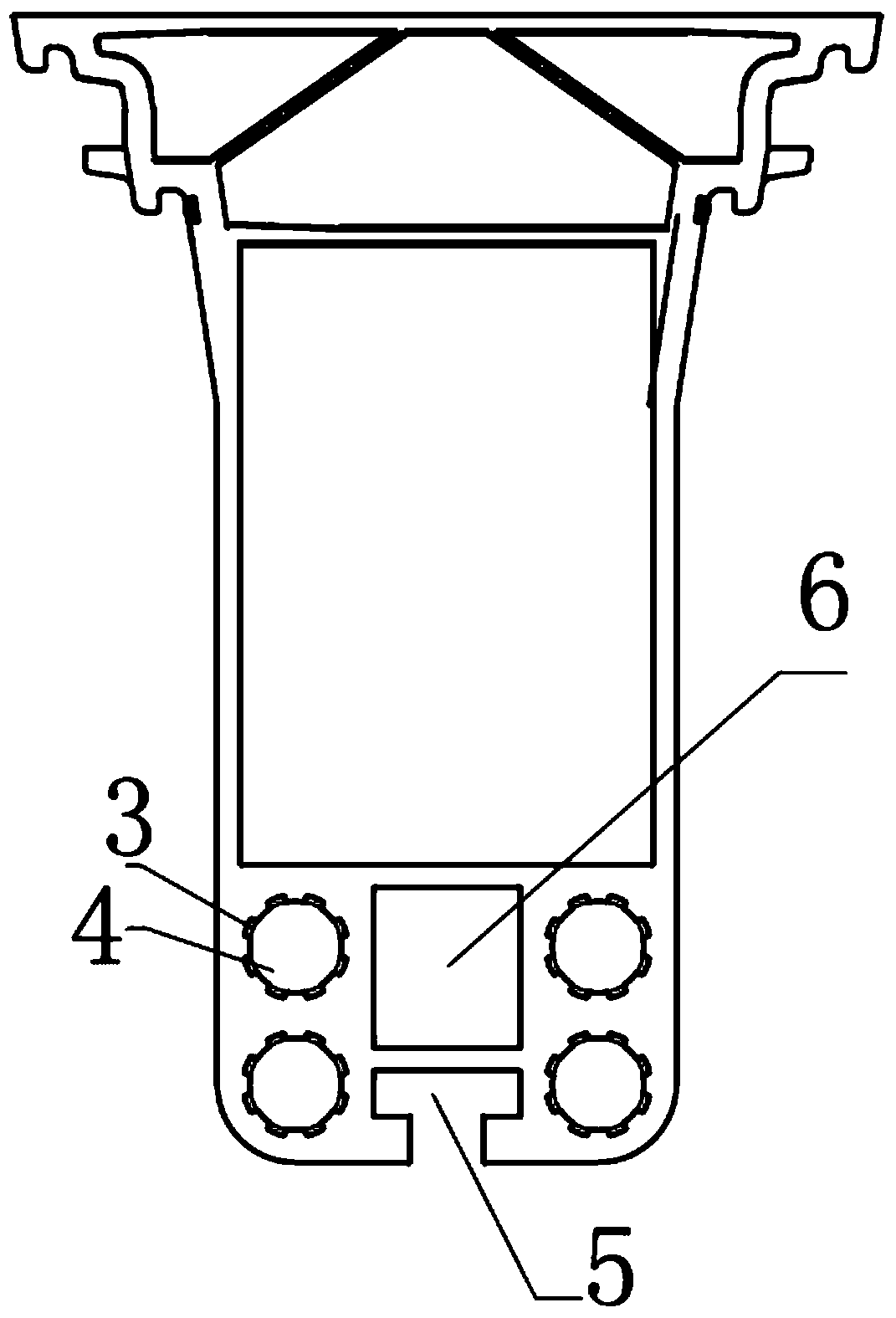
[0063] Such as Figure 1-6 As shown, a load template of this embodiment includes

[0064] The template body 1 has a pouring surface 7, an outer surface opposite to the pouring surface 7, and a connecting edge formed between the pouring surface 7 and the outer surface,

[0065] The outer side of the template body 1 is provided with a beam-shaped supporting body 2, and the supporting body 2 extends from one of the splicing edges of the template body 1 to the other splicing edge opposite to the splicing edge . In this embodiment, the supporting body 2 is a box-shaped structure.

[0066] The above-mentioned solution is the core solution of the present invention. By integrally forming the supporting body 2 on the back of the template body 1, the template has a load-bearing capacity. Using the supporting mechanism can not only achieve rapid turnover, improve the efficiency of cycle use, and save costs, but also because there is no need to set up a supporting structure, the struct...

Embodiment 2

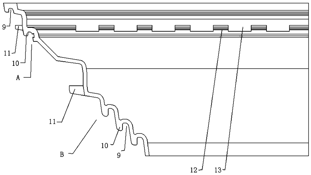
[0083] Such as Figure 7-13 As shown, the difference between this embodiment 2 and embodiment 1 lies in the second connection structure B. In this embodiment 2, the second connection structure B includes the adjacent template molded on the carrier body 2 Three first locking grooves 16 on the butt joint edge of the carrying bracket 2, the cross section of the first locking groove 16 is a shape with a narrow width at the notch and a wide width at the bottom of the groove, and the locking The surface is surrounded by the first locking groove 16 on the two butted supporting brackets 2, the cross-sectional shape of the locking key 8 and the cross-section surrounded by the two first locking grooves 165 The shapes are consistent, and the insertion end of the locking key 8 is set in a wedge shape. Of course, the number of the first locking grooves 16 is not limited to three, and can be set as required.

[0084] Figure 10 yes Figure 9 A simple deformation of , through this deforma...

Embodiment 3

[0086] Such as Figure 14-16 As shown, in this embodiment, the second connection structure B includes a second locking groove 17 and a second locking groove 17 molded on the connecting edge of the carrier body 2 that abuts with the adjacent carrier body 2 . A second locking projection 18, the cross section of the second locking groove 17 is narrow in width at the notch and wide in the bottom of the groove, the second locking groove 17 and the second locking projection 18 is adapted to cooperate with the corresponding second locking projection 18 and second locking groove 17 on the adjacent template. Likewise, the number of the second locking grooves 17 and the number of the second locking projections 18 can also be set according to needs. In order to ensure reliable connection, a wedge-shaped locking block 19 is driven between the second locking groove 17 and the second locking protrusion 18 inserted into the second locking groove 17 .

[0087] Figure 17 yes Figure 16 A ...


PUM


Abstract

The invention relates to a bearing formwork, comprising a formwork body which has a casting surface, an outer surface opposite to the casting surface and connecting edges formed between the casting surface and the outer surface. The outer surface of the formwork body is provided with a beam bearing support which extends from one joint edge of the formwork body to the other joint edge opposite to the joint edge. Part of the formwork body is provided a reinforcing pre-arranged structure extending along the length of the bearing support. The bearing formwork is imparted bearing capacity and a cavity requiring bearing force during setup, and in the case of a cavity of a bearing beam, no additional support mechanism is used, allowing quick turnover, improving cyclic service efficiency and saving cost; as no support structure is required, the structure is simpler, less spatial place is used, beam pre-arching is implemented, and strength of the formwork itself is further improved.

Description

technical field [0001] The invention relates to the construction field, in particular to a load-bearing formwork with load-bearing capacity. Background technique [0002] The construction of the cast-in-place concrete structure needs to assemble the corresponding temporary model structure according to the shape of the concrete structure required by the design. The temporary model structure is usually spliced ​​by a plurality of building templates according to a certain splicing method. However, in the prior art, the load-bearing strength of building formwork only considers the requirements of the formwork itself on the pressure of the pouring materials carried by it, but does not consider the overall load-bearing strength requirements of the assembled temporary model structure. When the current temporary model structure is assembled, the connection of the building formwork is only to form a temporary model structure through the mutual connection and splicing of the edge-and...

Claims


Application Information

Patent Timeline
Patent Type & Authority Patents(China)
IPC IPC(8): E04G9/00E04G17/00
Inventor 王斌坚章国荣
Owner NENGCHENG GRP
Why Eureka
Try Eureka