Hydraulic vibration type high-power wave generation system and control method thereof

A hydraulic vibration and high-power technology, which is applied in the direction of fluid pressure actuators, servo motors, hydraulic models, etc., can solve the requirements that cannot take into account the commutation frequency and flow rate of the wave-making system, and cannot simulate the desired waveform, Reversing valve slow response speed and other issues, to achieve the effect of small leakage, simple structure and sensitive action

Inactive Publication Date: 2016-04-20
NINGBO INST OF TECH ZHEJIANG UNIV ZHEJIANG
View PDF6 Cites 22 Cited by
  • Summary
  • Abstract
  • Description
  • Claims
  • Application Information

AI Technical Summary

Problems solved by technology

[0005] The existing wave-making system based on hydraulic drive usually adopts the reversing valve in the form of a spool valve. The reversing valve in the form of a spool valve has a slow response speed, and it is difficult to achieve a high reversing frequency and better reversing accuracy.
Regardless of whether the reversing valve in the form of a slide valve adopts electromagnetic reversing or hydraulic reversing, while the reversing frequency is limited, it is also limited by the flow rate, and it is impossible to take into account the wave-making system on the reversing frequency and flow rate. Requirements, so that the existing wave-making system cannot simulate the wave when the expected waveform is more complicated

Method used


Image

  • Hydraulic vibration type high-power wave generation system and control method thereof
  • Hydraulic vibration type high-power wave generation system and control method thereof

Examples


Embodiment Construction

[0032] The following will clearly and completely describe the technical solutions in the embodiments of the present invention with reference to the accompanying drawings in the embodiments of the present invention. Obviously, the described embodiments are some of the embodiments of the present invention, but not all of them. Based on the embodiments of the present invention, all other embodiments obtained by persons of ordinary skill in the art without making creative efforts belong to the protection scope of the present invention.

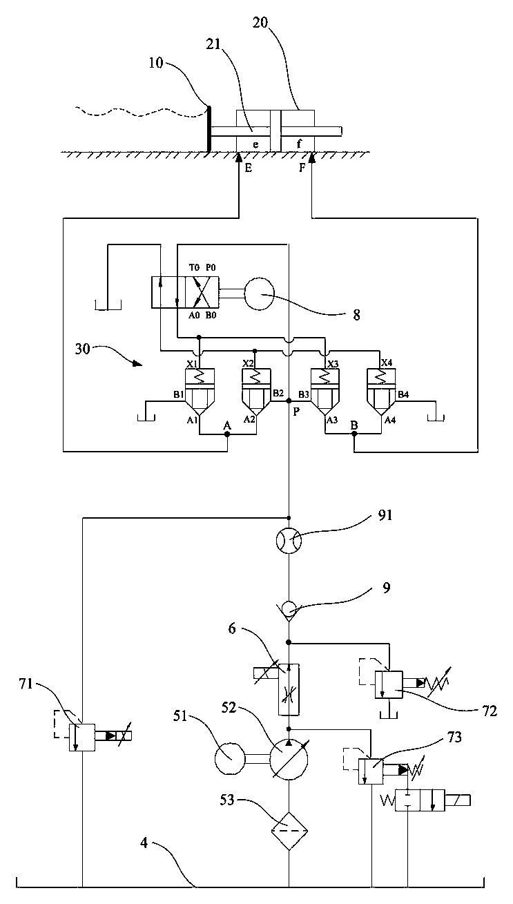
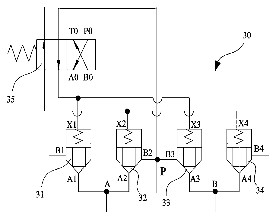
[0033] figure 1 A working principle diagram of the hydraulic vibration type high-power wave-making system described in the present invention is shown. like figure 1 As shown in , the hydraulic vibration high-power wave-making system includes a wave pusher 10 , a hydraulic cylinder 20 , a control valve group 30 , an oil supply device, a controller, an oil tank 4 , a speed regulating valve 6 and a stepping motor 8 . The wave pusher 10 is connected...


PUM


Abstract

The invention relates to a hydraulic vibration type high-power wave generation system and a control method thereof. The wave generation system comprises a wave pushing plate, a hydraulic cylinder, a control valve group, an oil supply device, a controller, a speed adjusting valve, a stepper motor and an oil tank; and the wave pushing plate is connected to a piston rod of the hydraulic cylinder, and can be driven to generate analog waves under linear reciprocating effect of the piston rod. A port A of the control valve groupis connected to a port E of the hydraulic cylinder; a port B of the hydraulic valve group is connected to a port F of the hydraulic cylinder; and the oil supply device can suck oil from the oil tank, and can supply the oil to the hydraulic cylinder through the control valve group. The wave generation system uses the control valve group, consisting of a valve element rotary reversing valve and four cartridge valves, for controlling the movement of the hydraulic cylinder, so that the wave generation system can havethe advantages of high reversing frequency control precision and wide control range of the valve element rotary reversing valve and high circulating capacity of the cartridge valves. The valve element rotary reversing valve is provided with a rotating valve element; and the stepper motor is connected to thevalve element of the valve element rotary reversing valve.

Description

technical field [0001] The invention belongs to the field of wave simulation, and in particular relates to a hydraulic vibration type high-power wave-making system and a control method thereof. Background technique [0002] In the fields of ships, ports, coastal engineering, ocean engineering, etc., wave-making technology is an important test technology, and the wave-making technology is simulated by the wave-making system as an important laboratory device. The wave-making system consists of a controller, a driving device and a wave pushing plate. Under the control of the controller, the driving device drives the wave pushing plate to move according to a certain control law, and the wave pushing plate pushes the fluid medium to form various forms of simulated waves. , used to study the effect of waves on water structures such as ships, docks and dams. [0003] According to the different driving devices, the wave-making system can be divided into two categories: the wave-mak...

Claims


Application Information

Patent Timeline
Patent Type & Authority Applications(China)
IPC IPC(8): F15B11/08F15B13/04F15B13/16E02B1/02
Inventor 刘毅俞育堃王登蒋余新王贤成陈俊华戚凯科龚国芳
Owner NINGBO INST OF TECH ZHEJIANG UNIV ZHEJIANG
Why Eureka
Try Eureka