Novel assembled type fan coupler

An assembled and coupling technology, applied in the direction of couplings, rigid shaft couplings, clutches, etc., can solve the problems of high noise, low production efficiency, easy failure, etc., and achieve the effect of avoiding damage and prolonging the service life

Active Publication Date: 2016-04-20
十堰风神汽车橡塑制品有限公司
View PDF7 Cites 3 Cited by
  • Summary
  • Abstract
  • Description
  • Claims
  • Application Information

AI Technical Summary

Problems solved by technology

[0003] One is that the inner and outer flanges are completely filled and connected with rubber vulcanization, and the rubber has the effect of damping vibration in the circumference, radial direction and axial direction, which has poor coaxiality of the assembly positioning circle, large dynamic unbalance, and large fan deflection. , the disadvantages of high noise and easy failure during operation; the other is that the inner and outer flanges are positioned with rigid spigots and filled with rubber vulcanization. The radial direction is completely rigid spigot connection, which sacrifices the radial vibration damping performance of the assembly. When the impact load is encountered, the vibration damping effect is not good, and it is easy to cause damage to related parts
Moreover, both structures have problems such as complicated production process and low production efficiency.
[0004] At the same time, the vulcanization of large-volume fan couplings requires a large mold cost and manufacturing pressure. The mold is large and its accuracy cannot be controlled and guaranteed.

Method used


Image

  • Novel assembled type fan coupler
  • Novel assembled type fan coupler
  • Novel assembled type fan coupler

Examples


Embodiment Construction

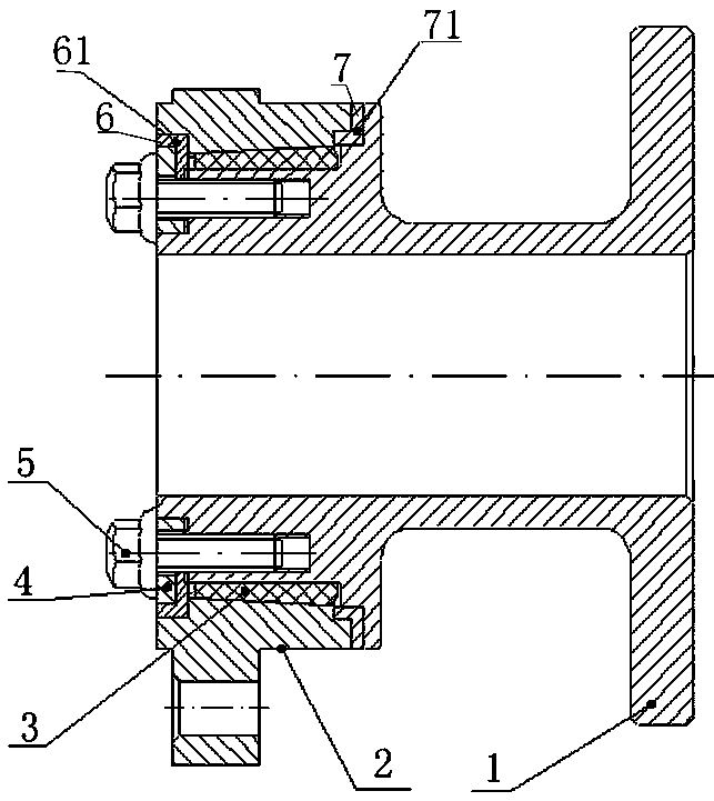
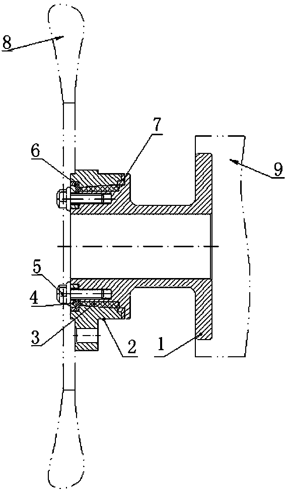
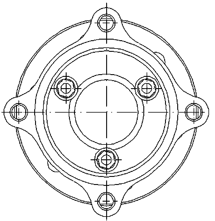
[0022] The present invention as figure 1 , figure 2 , image 3 shown.

[0023] A new type of assembled fan coupling, including an outer flange 1, an inner flange 2, the outer flange 1 is connected to the engine 9, the inner flange 2 is connected to the fan 8, the outer flange 1 and the inner flange 2 Both are equipped with an upper stop 6 and a lower stop 7, the outer flange 1 and the inner flange 2 are set together and form a cavity through the upper stop 6 and the lower stop 7, and a rubber shock absorber is installed inside the cavity 3. The outer flange 1 and the inner flange 2 are connected together through the bolt 5 and the end cover 4, and the rubber damping block 3 is press-fitted.

[0024] The cavity formed by the outer flange 1 and the inner flange 2 is a conical cavity, wherein the taper of the conical cavity faces the direction of the end cover 4, and the corresponding rubber shock absorber 3 is also taper in the same direction; the rubber shock absorber 3 he...


PUM


Abstract

The invention provides a novel assembled type fan coupler which comprises an outer flange and an inner flange. The outer flange is connected with an engine. The inner flange is connected with a fan. The outer flange and the inner flange are each provided with an upper spigot and a lower spigot. The outer flange and the inner flange are sleeved together and form a cavity through the upper spigots and the lower spigots. A rubber damping block is arranged in the cavity in a pressed mode. The outer flange, the inner flange and an end cover are connected into a whole through bolts and achieve press fitting of the rubber damping block. The cavity formed by the outer flange and the inner flange is a conical cavity. The taper of the conical cavity faces towards the end cover, and correspondingly, the taper of the rubber damping block is in the same direction. The rubber damping block highly presets compression amount. The coaxiality and the accuracy of depth of parallelism of the product can be ensured, the damping performance in circumferential direction, radial direction, axial direction and the like of the coupler is achieved, and therefore the system stability and reliability are improved.

Description

technical field [0001] The invention relates to the technical field of fan couplings of automobile cooling systems, and particularly proposes a novel assembled fan coupling for connecting an engine transmission shaft and a fan. Background technique [0002] Most of the fan couplings in the current engine cooling system are integral, and there are basically two states. [0003] One is that the inner and outer flanges are completely filled and connected with rubber vulcanization, and the rubber has the effect of damping vibration in the circumference, radial direction and axial direction, which has poor coaxiality of the assembly positioning circle, large dynamic unbalance, and large fan deflection. , the disadvantages of high noise and easy failure during operation; the other is that the inner and outer flanges are positioned with rigid spigots and filled with rubber vulcanization. The radial direction is completely rigid spigot connection, which sacrifices the radial vibrat...

Claims


Application Information

Patent Timeline
Patent Type & Authority Applications(China)
IPC IPC(8): F16D1/076
CPCF16D1/076F16D2300/12F16D2300/22
Inventor 曹文罗华强党鸿远王伟李绍春
Owner 十堰风神汽车橡塑制品有限公司
Why Eureka
Try Eureka