A hydraulic clutch device

A clutch device and hydraulic technology, applied in clutches, fluid-driven clutches, non-mechanical-driven clutches, etc., can solve the problems of the layout occupying the internal space of the machine, the complex connecting rod structure, and the troublesome assembly, so as to reduce the work intensity and achieve a compact and reasonable structure. , the effect of improving work efficiency

Active Publication Date: 2018-02-16
JIANGSU WUXI MINERAL EXPLORATION MASCH GENERAL FAB CO LTD
View PDF6 Cites 0 Cited by
  • Summary
  • Abstract
  • Description
  • Claims
  • Application Information

AI Technical Summary

Problems solved by technology

[0003] Most of the starting devices commonly used in the prior art use a connecting rod structure. Although it can reduce the labor intensity of workers to a certain extent, due to the complicated structure of the connecting rod and many parts, it is more troublesome to assemble. It also takes up more space inside the machine

Method used


Image

  • A hydraulic clutch device
  • A hydraulic clutch device
  • A hydraulic clutch device

Examples


Embodiment Construction

[0022] The present invention will be further described below in conjunction with specific drawings and embodiments.

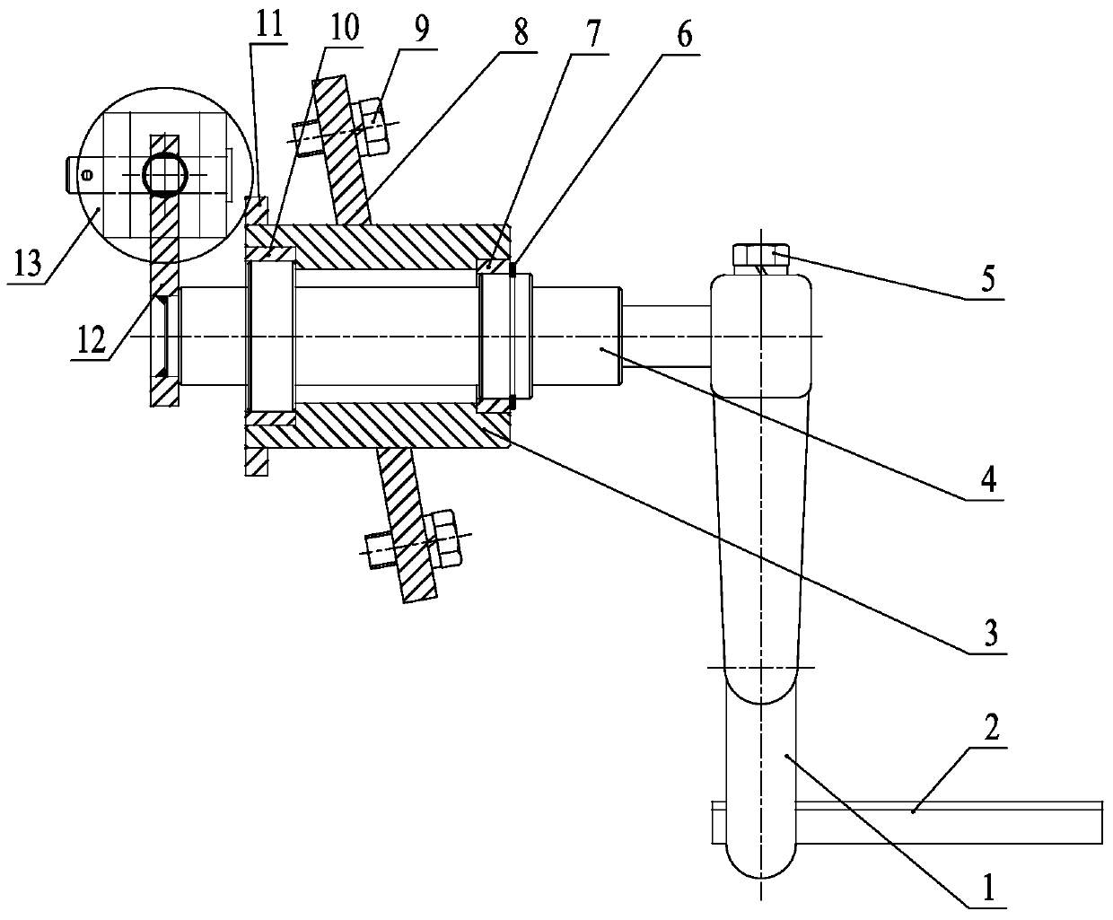
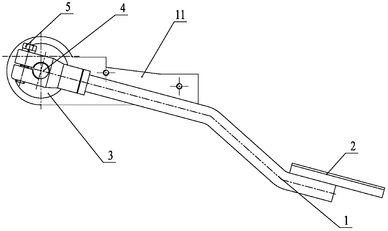
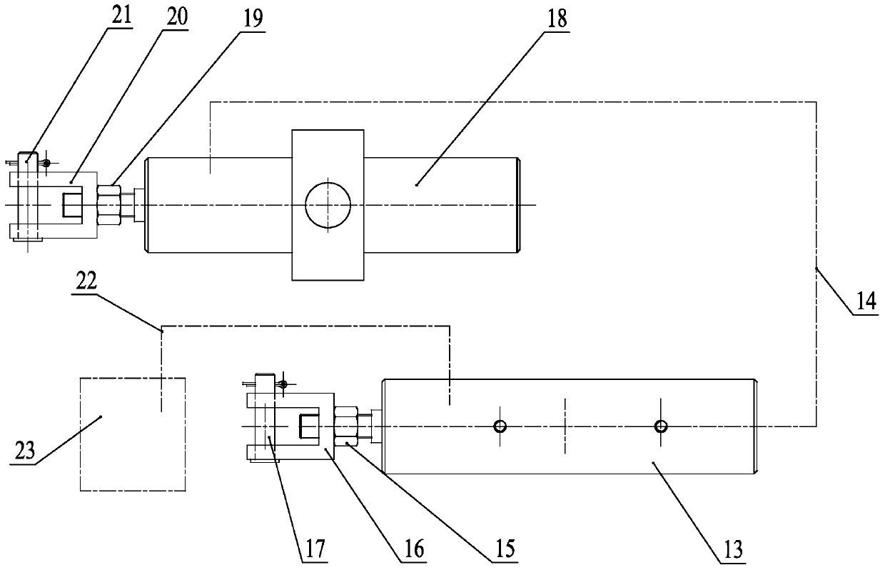
[0023] As shown in the figure: the hydraulic clutch device in the embodiment is mainly composed of a pedal rod 1, a pedal 2, a rotating shaft 4, a bracket body 3, a first bolt 5, a retaining ring 6, a first bushing 7, and a bracket plate 8. The second bolt 9, the second shaft sleeve 10, the fixed plate 11, the convex plate 12, the clutch oil cylinder 13, the first oil delivery pipe 14, the first lock nut 15, the first turning handle 16, the first pin 17, the automatic Resetting oil cylinder 18, the second locking nut 19, the second rotating handle 20, the second pin 21, the second oil delivery pipe 22 and oil reservoir 23 etc. are composed.

[0024] Such as Figure 1~Figure 7 As shown, the rotating shaft 4 is supported and installed in the bracket body 3 through a rotating support assembly, one end of the pedal rod 1 is fixedly installed on the right end of th...


PUM


Abstract

The invention relates to a hydraulic engaging and disengaging gear. A rotary shaft is installed in a bracket through supporting of a rotary supporting assembly, one end of a foot rest lever is fixedly installed at the right end of the rotary shaft, and the other end of the foot rest lever is connected with a pedal plate. A fixing plate is arranged on the bracket, and a cylinder body of an engaging and disengaging oil cylinder is fixed to the fixing plate. An inverted-T-shaped plate is fixed to the left end of the rotary shaft, and the piston rod end of the engaging and disengaging oil cylinder is hinged to the tail end of the inverted-T-shaped plate through a first joint assembly. An upper oil opening of the engaging and disengaging oil cylinder is communicated with an oil reservoir through a second oil conveying pipe, and a lower oil opening of the engaging and disengaging oil cylinder is communicated with an upper oil opening of an automatic reset oil cylinder through a first oil conveying pipe. The piston rod end of the automatic reset oil cylinder is connected with a clutch through a second joint assembly. The hydraulic engaging and disengaging gear is compact and reasonable in structure, the clutch runs through hydraulic transmission, the braking response of the clutch is rapid, the working intensity of operators can be greatly relieved, and working efficiency is improved.

Description

technical field [0001] The invention relates to a hydraulic clutch device, which realizes the operation of the clutch through hydraulic action, and belongs to the technical field of construction machinery foundation equipment. Background technique [0002] Clutches are often used in modern large-scale mechanical equipment such as some drilling rigs, and the clutches they carry are equipped with high-strength springs inside. Because the springs are relatively strong, it is difficult for manpower to make them work. For this reason, a starting device is used to operate the clutch through hydraulic action. [0003] Most of the starting devices commonly used in the prior art use a connecting rod structure. Although it can reduce the labor intensity of workers to a certain extent, due to the complicated structure of the connecting rod and many parts, it is more troublesome to assemble. It also takes up more space inside the machine. Contents of the invention [0004] The purpo...

Claims


Application Information

Patent Timeline
Patent Type & Authority Patents(China)
IPC IPC(8): F16D25/12
CPCF16D25/12
Inventor 朱利根
Owner JIANGSU WUXI MINERAL EXPLORATION MASCH GENERAL FAB CO LTD
Why Eureka
Try Eureka