Ice conveying system for refrigerator

A technology for conveying systems and refrigerators, applied in applications, making ice, household appliances, etc. It can solve the problems of complex structure of ice conveying systems, high motor requirements, and difficult separation, and achieve enhanced ice stirring effect, low power requirements, and increased The effect of ice storage

Active Publication Date: 2016-04-20
HEFEI HUALING CO LTD +1
View PDF9 Cites 12 Cited by
  • Summary
  • Abstract
  • Description
  • Claims
  • Application Information

AI Technical Summary

Problems solved by technology

[0004] The technical problem to be solved by the present invention is: in order to solve the problem that the ice cubes in the ice conveying system of the existing refrigerator are not easy to separate after they are stuck together, the ice can only be sent out of the ice storage box through the operation o

Method used


Image

  • Ice conveying system for refrigerator
  • Ice conveying system for refrigerator
  • Ice conveying system for refrigerator

Examples


Embodiment 1

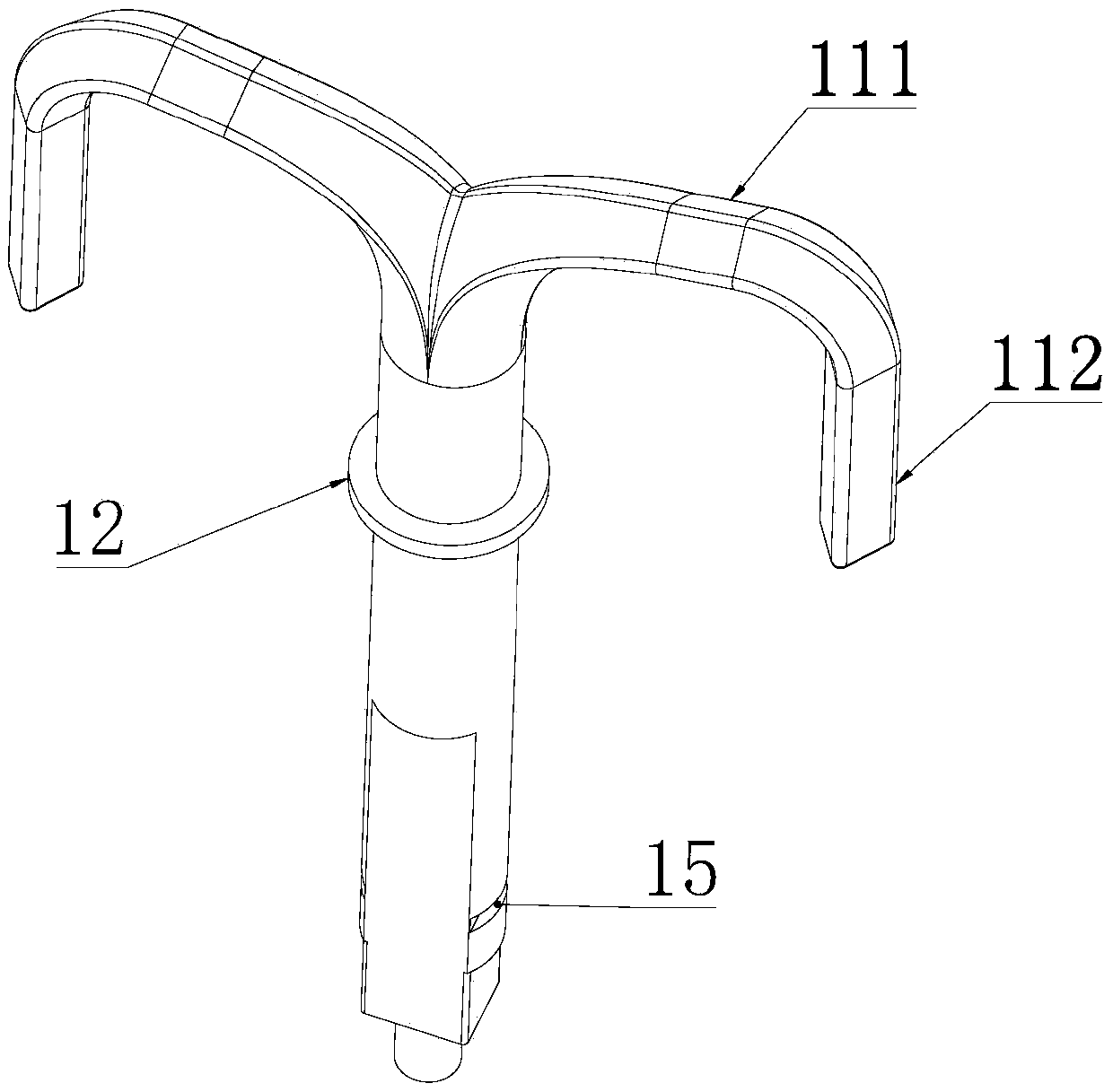
[0035] Based on the above, such as figure 2 with 3 As shown, in this embodiment, the second branch 112 and the rod body are located on the same side of the first branch 111 . That is, the second branch 112 is bent downward relative to the first branch 111 . This structure can be used when the first branch 111 is at a higher position in the ice storage box 3 and there are more ice cubes below it, and the second branch 112 is bent downward to help stir the ice in the lower part of the ice storage box 3 blocks to prevent dead ends.

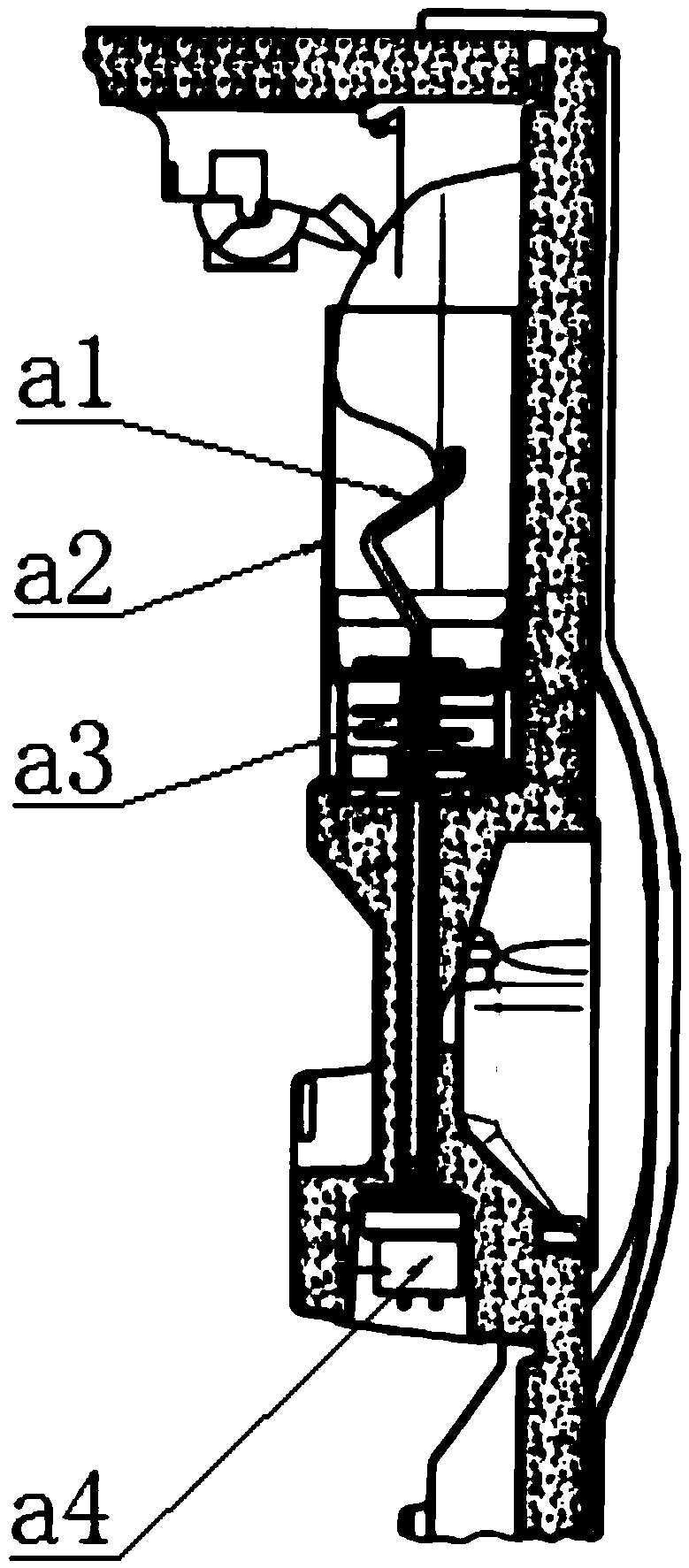
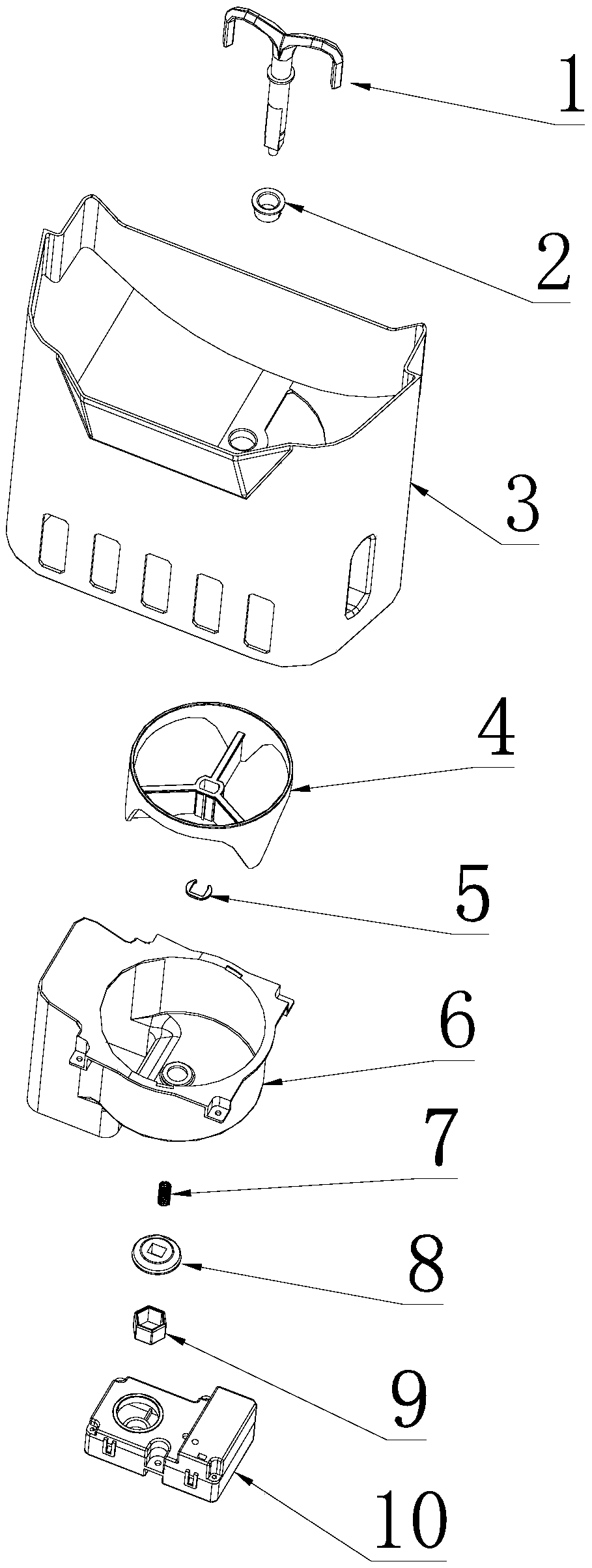
[0036]Below the ice storage box 3 is connected an ice outlet passage 6 connected with the ice outlet, and the ice outlet passage 6 is provided with an ice selection cylinder 4, and the ice selection cylinder 4 is arranged on the side of the ice outlet. Below, the ice selection cylinder 4 is used to transport the ice cubes from the ice outlet to the outlet of the ice outlet channel 6 by rotating; the rod body passes through the ice storage box 3, ...

Embodiment 2

[0043] This embodiment is basically the same as Embodiment 1, the only difference is that, as Figure 4 with 5 As shown, the second branch 112 and the rod body are respectively located on two sides of the first branch 111 . That is, the second branch 112 is bent upward relative to the first branch 111 . This structure can be used when the first branch 111 is at a lower position in the ice storage box 3 and there are more ice cubes above it, and the second branch 112 is bent upwards to help stir the ice cubes on the upper part of the ice storage box 3 , to prevent dead ends.


PUM


Abstract

The invention belongs to the technical field of ice distribution and conveying, and discloses an ice conveying system for a refrigerator. The ice conveying system comprises an ice stirring rod, an ice storage box and a motor, wherein an ice outlet is formed in the bottom wall of the ice storage box; the lower end of the ice stirring rod penetrates through the bottom wall of the ice storage box, and is connected with the motor; the ice stirring rod comprises a rod body, and a plurality of branches arranged at the top end of the rod body and uniformly distributed by winding the rod body; the cutting side of each branch adopts a blade structure. Through the adoption of the ice stirring rod of which the cutting surface of each branch adopts the blade structure, the resistance of the ice stirring rod and ice blocks is relatively small, and the ice blocks can be successfully pushed out of the ice storage box without the ice crushing operation; the purposes of separating the ice blocks and pushing the ice blocks to move are realized at the same time in the ice stirring process, the ice blocks bonded together can be discharged from the ice outlet after being separated, the ice crushing operation is avoided, the structure of ice stirring equipment is greatly simplified, the ice storage amount of the ice storage box is increased, requirements on power of the motor for driving the ice stirring rod are relatively low, and the manufacturing cost is reduced.

Description

technical field [0001] The invention relates to the technical field of ice distribution and delivery, in particular to an ice delivery system for a refrigerator. Background technique [0002] In the existing automatic ice-making equipment for refrigerators, the ice cubes in the ice storage box are easy to stick together, resulting in high resistance to ice cube transportation, and the ice cubes need to be crushed by crushing ice before being sent out. For example, the U.S. Patent Publication No. US6082130A discloses an ice delivery system for a refrigerator, such as figure 1 As shown, in order to facilitate sending ice out of the ice storage box a2, an ice crushing device a3 is provided; in order to reduce space occupation, the ice stirring rod a1 is connected with the ice crushing device a3 and driven by the same motor a4. The driving force is relatively large, and the configuration requirements for the motor a4 are relatively high; although the ice stirring rod a1 and the...

Claims


Application Information

Patent Timeline
IPC IPC(8): F25C5/02
CPCF25C5/02
Inventor 杨广卿王浩吕正光
Owner HEFEI HUALING CO LTD
Why Eureka
Try Eureka