A spinning machine for polypropylene processing

A polypropylene and spinning machine technology, applied in the polypropylene field, can solve the problems of disconnection and large internal space of the spinneret, and achieve the effect of avoiding cleaning

Active Publication Date: 2022-07-08
山东东泰力特新材料科技有限公司
View PDF5 Cites 0 Cited by
  • Summary
  • Abstract
  • Description
  • Claims
  • Application Information

AI Technical Summary

Problems solved by technology

[0003] Due to the large internal space of the spinneret of the spinning machine for polypropylene, if the molten polypropylene added at one time is not enough to fill the spinneret, the spinneret has already pushed the molten polypropylene forward for spinning, so that As for the second batch of molten polypropylene raw materials introduced into the spinneret, there will be a gap between the two batches of molten polypropylene that cannot be connected, so that the spinning of the polypropylene spinning machine will be disconnected in the middle.

Method used


Image

  • A spinning machine for polypropylene processing
  • A spinning machine for polypropylene processing
  • A spinning machine for polypropylene processing

Examples


Embodiment 1

[0026] For example figure 1 -example Figure 5 Shown:

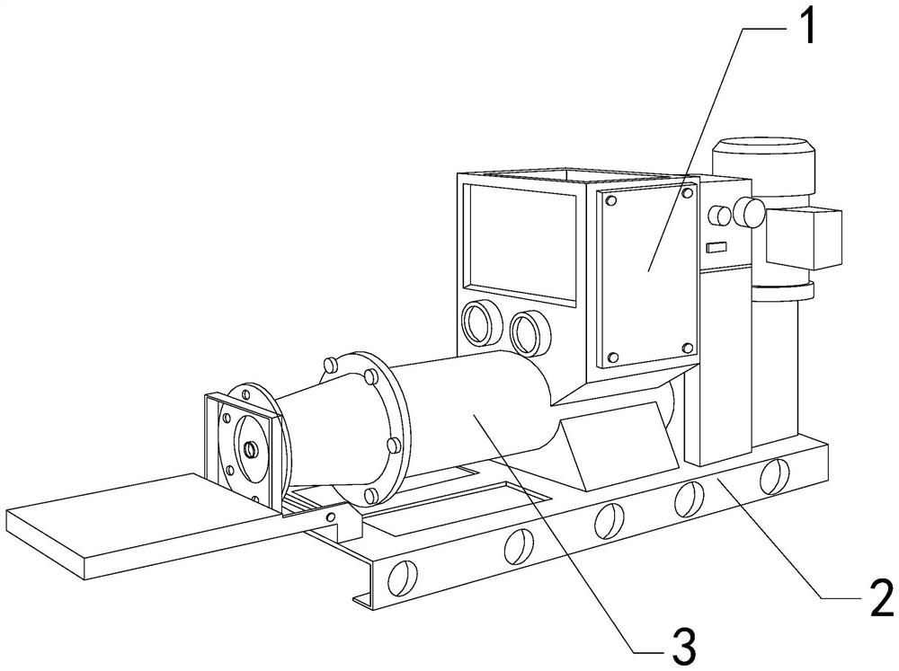
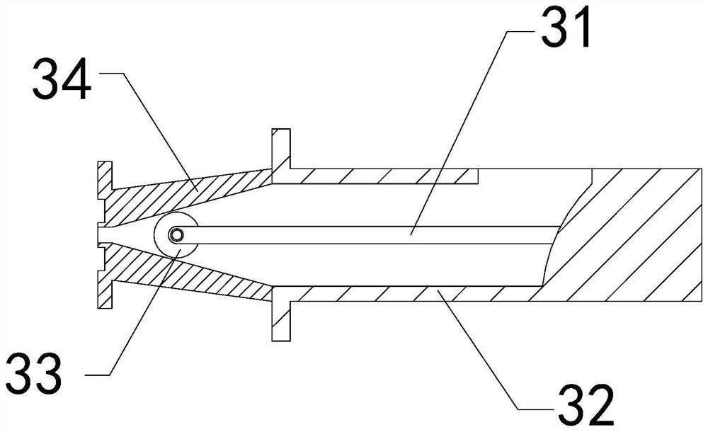
[0027] The present invention provides a spinning machine for polypropylene processing. The internal position of the heating bucket 1; the spinneret tube 3 includes a middle fixing rod 31, an outer tube 32, a take-out mechanism 33, and a pre-pipe 34. The middle fixing rod 31 is embedded in the right position of the inner wall of the outer tube 32. , the take-out mechanism 33 is movably engaged with the left end of the middle fixing rod 31 , and the right side of the front pipe 34 is abutted with the left side of the middle fixing rod 31 .

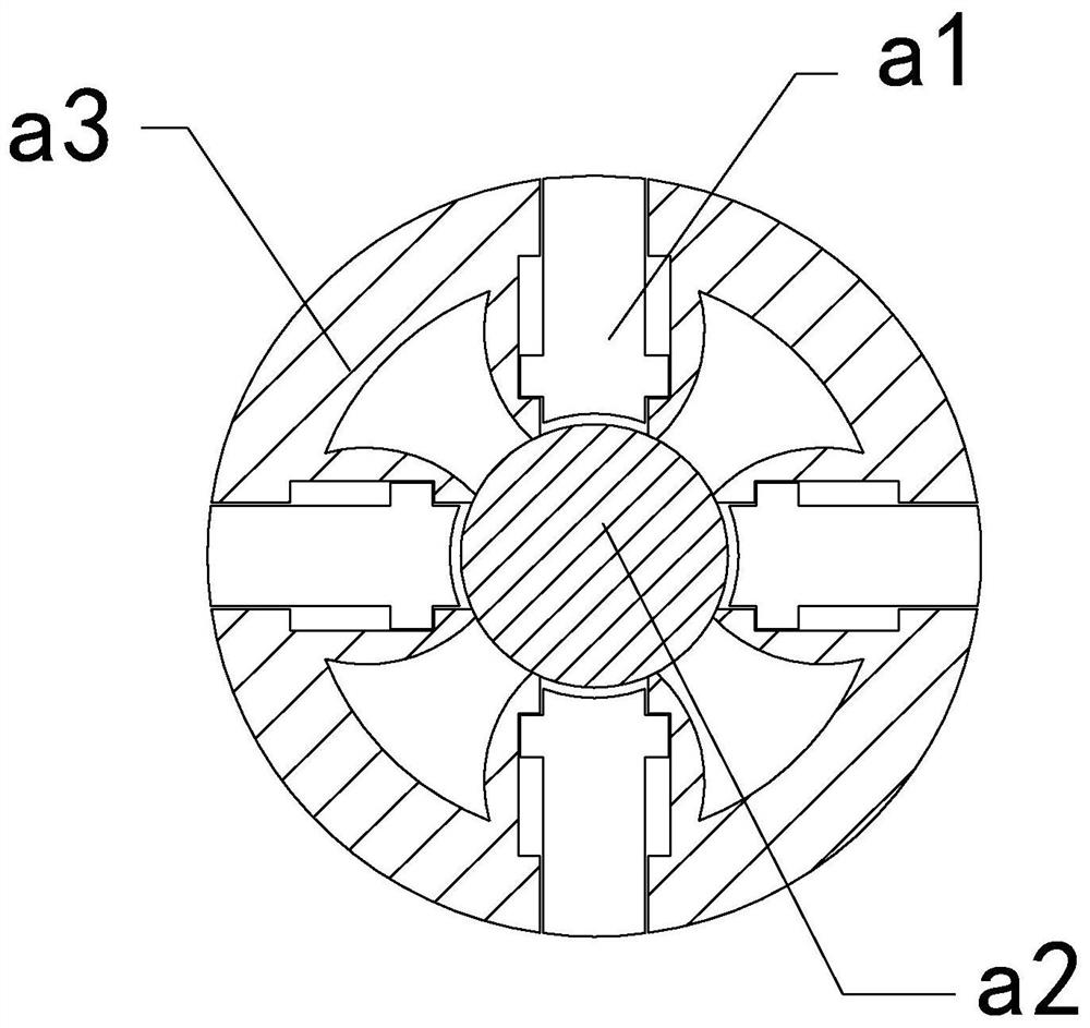
[0028] The take-out mechanism 33 includes an outrigger rod a1, a middle solid block a2, and an outer ring a3, the outer extension rod a1 and the inside of the outer ring a3 are distributed in parallel, and the middle solid block a2 is fixed on the outer ring a3 The inner center position of the outriggers a1 is provided with four, and evenly distributed in a circle inside the outer ri...

Embodiment 2

[0034] For example Image 6 -example Figure 8 Shown:

[0035] The outer ring a3 includes an outer expansion plate c1, a fixed frame c2, a middle block c3, and an elastic piece c4. The outer expansion plate c1 is connected to the outer side of the fixed frame c2 through the elastic piece c4, and the fixed frame c2 It is fixed at the position of the outer surface of the neutral block c3. There are four outer expansion plates c1, and they are evenly distributed in a circle on the outside of the fixed frame c2. The force generated by the rotation of the mechanism can make the outer expansion plates c1 Extending out along the elastic sheet c4, and then pulling the outer expansion plate c1 by the elastic sheet c4, the inner side of the outer expansion plate c1 can generate impact vibration to the outer side of the fixed frame c2.

[0036] The outer expansion plate c1 includes a base plate c11, a vibration ball c12, an outer contact plate c13, and a contact reduction groove c14. T...


PUM


Abstract

The invention discloses a spinning machine for polypropylene processing. Its structure includes a heating bucket, a base and a spinneret. The heating bucket is welded on the upper surface of the base. The spinneret runs through the inner position of the heating bucket and extends through the outside The inertial force generated by the rod extending outward can make the extension block slide upward along the bottom frame on the linkage rod, so that the stirring groove can increase the stirring range of the molten polypropylene inside the spinneret, so the extension The rod can agitate and mix two batches of molten polypropylene together with the cooperation of the stirring tank, which effectively avoids the gap between the two batches of molten polypropylene introduced into the spinneret at different times. When the take-out mechanism stops rotating Afterwards, the outer expansion plate can be pulled and contracted outward by the elastic sheet, so that the inner side of the outer expansion plate can be vibrated by the impact of the fixed frame, so that the vibration generated by the outer expansion plate can push the molten polypropylene attached to the outer surface of the outer expansion plate. fall.

Description

technical field [0001] The invention relates to the field of polypropylene, in particular to a spinning machine for polypropylene processing. Background technique [0002] The polypropylene spinning machine is mainly used for jet spinning of polypropylene. The polypropylene raw material is heated into a molten state through a heating hopper, and then the molten polypropylene raw material is sprayed out in a filamentary form through a spinneret. Finally, the polypropylene spinning is collected by the spinning machine to prepare for spinning and fabricating. Based on the above description, the inventor found that the existing spinning machine for polypropylene processing mainly has the following deficiencies, such as: [0003] Because the inner space of the spinneret of the polypropylene spinning machine is large, if the molten polypropylene added at one time is not enough to fill the spinneret, the molten polypropylene will be pushed forward by the spinneret for spinning, so ...

Claims


Application Information

Patent Timeline
Patent Type & Authority Patents(China)
IPC IPC(8): D01D1/00D01D13/00D01D4/00
CPCD01D1/00D01D13/00D01D4/00Y02P70/62
Inventor 李赛峰
Owner 山东东泰力特新材料科技有限公司
Why Eureka
Try Eureka