Detachable jet aerator and using method thereof

A jet aeration, split-type technology, applied in the direction of chemical instruments and methods, water aeration, fluid mixer, etc., can solve the problems of not attracting enough attention, poor quality of air bubbles, reduction of air intake, etc., and achieve reasonable Effect of using input energy, increasing agitation range, and improving bubble quality

Active Publication Date: 2009-09-30
TONGJI UNIV ARCHITECTURAL DESIGN INST GRP CO LTD
View PDF4 Cites 0 Cited by
  • Summary
  • Abstract
  • Description
  • Claims
  • Application Information

AI Technical Summary

Problems solved by technology

[0003] However, the design of this type of jet aerator is relatively complicated. Improper design can easily lead to small air intake, poor quality of bubbles, low power efficiency, and affect the cost of water treatment. This has become the main "bottleneck" of the engineering promotion and application of this type of jet aerator "
At the same time, since the basic structure of this type of jet aerator was proposed, the research on the new type of jet aerator, especially the outflow mode and outflow parts, and the optimization design of the structural parameters of the jet aerator have not attracted enough attention in recent years. Attention, there are relatively few researches and applications on this equipment
The most common is the direct discharge of the tailpipe, which is simple in form, but the energy utilization is unreasonable, the air bubbles are not fully utilized, and ultimately affect the cost of aeration; there are also perforated pipes added after the tailpipe, in order to reduce the suction The air quickly dissolves in the water to improve the oxygenation capacity of the jet aeration, but adding a perforated tube will increase the flow resistance, affect the suction performance of the jet, and is also prone to blockage; there are also L-shaped two-phase flow tubes and Serpentine coils, these two types of tortuous pipes, have the advantage of causing more turbulent opportunities than straight pipes to increase the dissolution and absorption of oxygen, but increase the flow resistance and reduce the intake air volume, so it does not commonly used

Method used


Image

  • Detachable jet aerator and using method thereof
  • Detachable jet aerator and using method thereof
  • Detachable jet aerator and using method thereof

Examples


Embodiment Construction

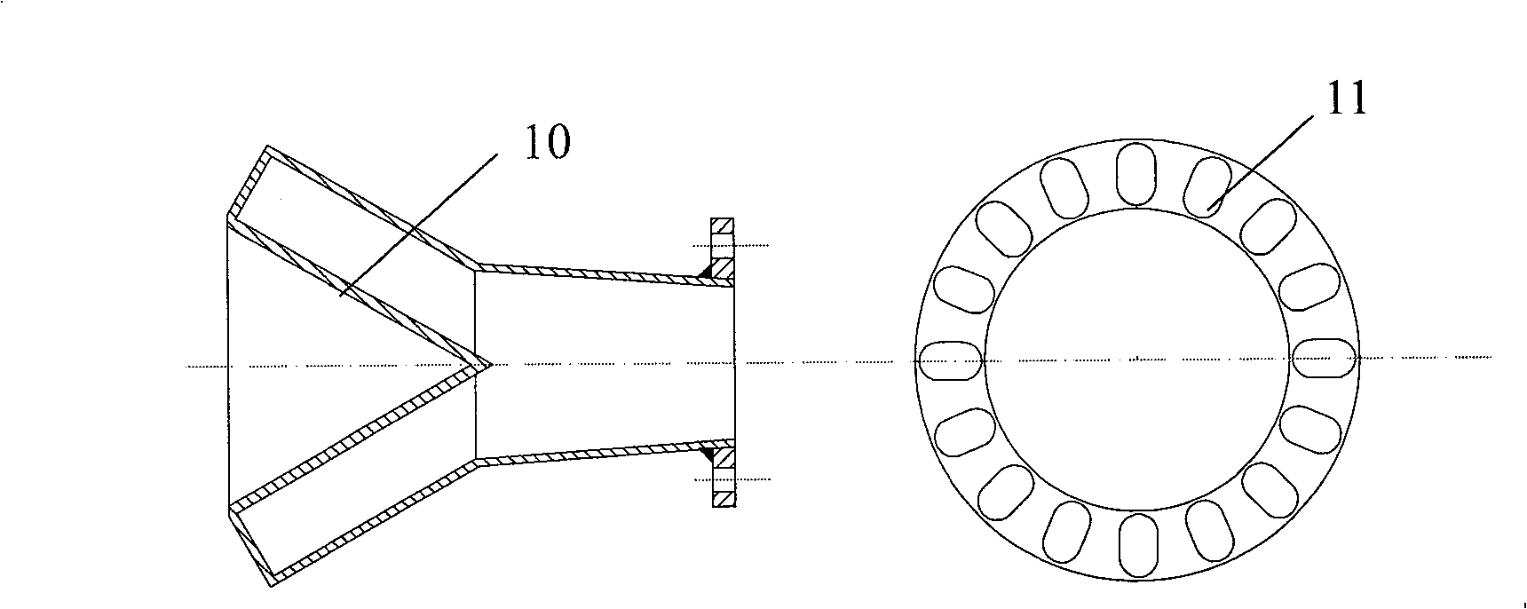
[0025] The research on the water distributor is an innovative point, and the name of the water distributor is generally called by the researchers according to its function. Its main function is to balance the contradiction between suction performance and agitation performance, promote the oblique and uniform flow of the three-phase mixed liquid, increase the agitation range of the jet aerator, and transfer the input energy to a wider water body, so as to achieve The purpose of rational utilization of input energy and energy saving.

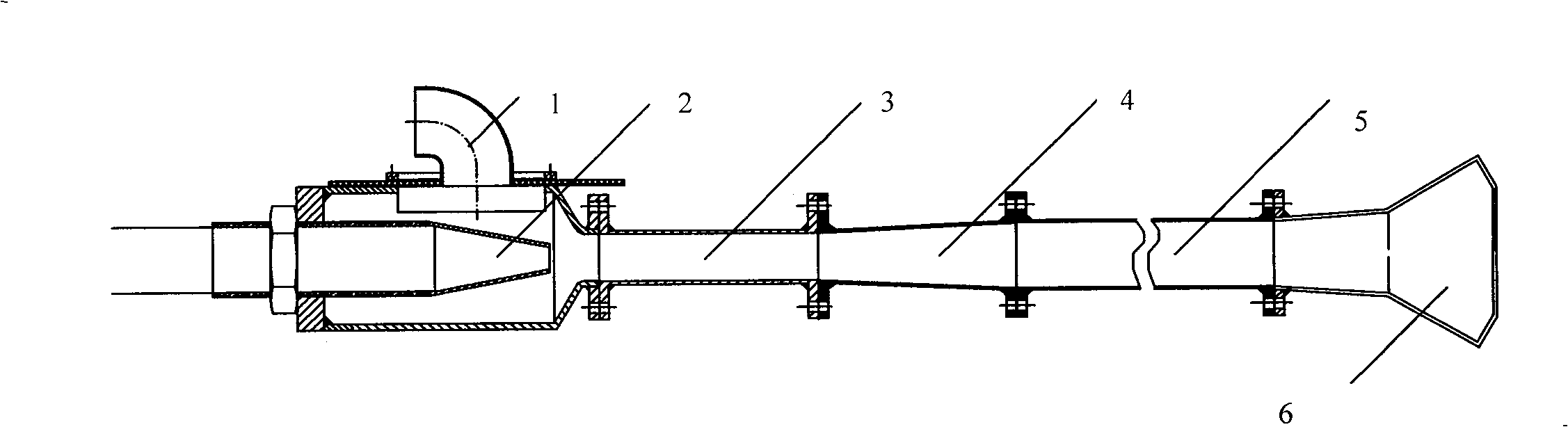
[0026] Specific working conditions: the water distributor 6 is installed at the rear of the tailpipe 5 and is connected by a flange, which is convenient for disassembly and maintenance. When working, when the gas-liquid foam flow enters the water distributor 6 through the tail pipe 5, because the internal design is equipped with a cone 10 with a certain angle, the flow of the mixed liquid will be deflected and flow from the water distributor at a ...


PUM


Abstract

The invention discloses a split jet aerator, which comprises the following parts: suction inlet, water nozzle, mixing tube, dispersing pipe, tail pipe and distributor, wherein the distributor connects the tail pipe; a cone with the action of deflecting the composite liquid and reducing the local resistance is set in the pipe segment with diffusing angle of tail pipe; the CFD company adopts artificial software value to optimize the design of the structure of jet aerator, which transmits the composite liquid of effluent-living sludge into water nozzle; certain vacuum is formed in the course of jet to form three-phased composite liquid of gas, liquid and solid, which enters into the dispersing pipe to form jet distributor with certain pressure to do inclined ejection to aerate oxygen and stir. The invention improves more dynamic efficiency and more oxygen utility than traditional one, which possesses larger suction quantity, higher bubble quality, evener stirring power and more energy saving.

Description

technical field [0001] The invention belongs to the field of water treatment and relates to an aeration device. Background technique [0002] Jet aeration (self-priming) is used in small wastewater and industrial wastewater treatment projects. Compared with microporous aerators, it has low investment, no need to install fans and air purification, good agitation effect, high oxygen utilization rate, and is not easy to block. It has the advantages of convenient maintenance, low noise and convenient installation. [0003] However, the design of this type of jet aerator is relatively complicated. Improper design can easily lead to small air intake, poor quality of bubbles, low power efficiency, and affect the cost of water treatment. This has become the main "bottleneck" of the engineering promotion and application of this type of jet aerator ". At the same time, since the basic structure of this type of jet aerator was proposed, the research on the new type of jet aerator, es...

Claims


Application Information

Patent Timeline
Patent Type & Authority Patents(China)
IPC IPC(8): B05B7/04B05B7/08B05B1/06B05B1/26B05B1/14B05B1/22B01F5/02C02F3/02C02F3/12C02F7/00
CPCY02W10/10
Inventor 顾国维张亚雷赵建夫吴勇高激飞赵子龙
Owner TONGJI UNIV ARCHITECTURAL DESIGN INST GRP CO LTD
Why Eureka
Try Eureka