Eureka AIR delivers breakthrough ideas for toughest innovation challenges, trusted by R&D personnel around the world.

Compound loading test system for power transmission infrastructure

A loading test and composite technology, which is applied in the testing of mechanical components, testing of machine/structural components, measuring devices, etc., can solve the problem of unseen composite loading test methods, low test accuracy, and unseen composite loading tests. System and other issues, to achieve the effect of improving overall maneuverability, improving test accuracy, and avoiding manual loading

Active Publication Date: 2016-04-20
NORTHEAST DIANLI UNIVERSITY
View PDF7 Cites 6 Cited by
  • Summary
  • Abstract
  • Description
  • Claims
  • Application Information

AI Technical Summary

Problems solved by technology

[0004] It can be seen that in the above-mentioned experimental studies, the vertical load and the horizontal load are mostly combined, or only the vertical uplift load and the download load are considered to test the bearing capacity of the transmission foundation, and the loading method is also mostly using the ground anchor reaction frame and Jack combination, or artificial stacking type, etc., the test accuracy is not high
At present, there is no composite loading test method that can apply vertical load, horizontal load and bending moment load in the published literature, and there is no test system that can realize the above-mentioned composite loading for the transmission foundation

Method used


Image

  • Compound loading test system for power transmission infrastructure
  • Compound loading test system for power transmission infrastructure
  • Compound loading test system for power transmission infrastructure

Examples


Embodiment Construction

[0031] The present invention will be further described below in conjunction with the accompanying drawings and embodiments.

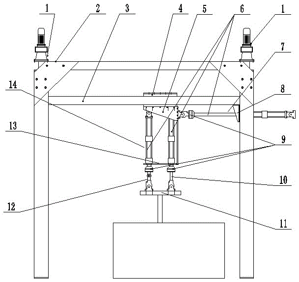
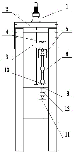
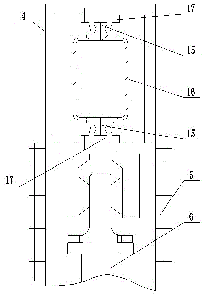
[0032] see Figure 1 to Figure 6, the present embodiment is used for the composite loading test system of power transmission foundation, and it comprises rigid frame 2, vertical lifting device 1 and vertical mobile platform 3, described rigid frame 2 is the fixed beam supported by four columns, two groups of vertical lifting devices 1 are respectively placed on both sides of the rigid frame 2, the upper end of the vertical lifting device 1 is fixedly connected to the fixed beam of the rigid frame 2, and the lower end is hinged to the rigid frame 2, and the vertical mobile platform 3 is placed in the rigid frame 2, and the two ends are respectively connected to the vertical The lifting device 1 is fixed, and also includes a vertical guide device, a horizontal guide device, a horizontal moving frame 4, a horizontal loading device 7, a vertical loading dev...


PUM


Abstract

The invention discloses a compound loading test system for a power transmission infrastructure. The compound loading test system for the power transmission infrastructure comprises a rigid frame, and is characterized by also comprising a vertical guide device; the vertical guide device and the rigid frame are fixedly connected with a vertical mobile platform; a horizontal guide device is placed on the vertical mobile platform and is fixedly connected with the vertical mobile platform; a horizontal mobile frame is fixedly connected with the horizontal guide device in a sleeving manner; a vertical loading device is placed at the lower end of the horizontal mobile frame and is fixedly connected with the lower end of the horizontal mobile frame; a horizontal loading device is hinged to the vertical loading device; a test piece clamp is placed below the vertical loading device and is hinged to the vertical loading device. When the compound loading test system for the power transmission infrastructure works: (1) the horizontal loading device applies horizontal force or horizontal displacement to a test component; (2) the vertical loading device provides the same vertical load to act on the test component directly; (3) the vertical loading device applies different vertical displacement to realize moment loading; (4) the pre-applied three-component load is split to obtain a loading displacement function, so as to realize a compound action of a horizontal load (H), a vertical load (V) and a moment load (M).

Description

technical field [0001] The test equipment involved in the present invention is a composite loading test system that can simultaneously apply horizontal load (H), vertical load (V) and moment load (M) to the test components of the power transmission foundation. Background technique [0002] The large-scale development of high-voltage transmission network construction has made the structure system of transmission towers increasingly high and flexible. The tower structure not only bears the long-term effects of the tower body, wires, ground wires, fittings, wind loads, etc., but also suffers from storms, ice loads, and disconnection loads. The instantaneous or short-term action of the special environment, etc., the load situation is complicated. These load effects are transmitted to the foundation and foundation, so that the tower foundation bears not only vertical tensile and compressive vertical loads (V), but also large horizontal loads (H) and bending moments (M). Usually,...

Claims


Application Information

Patent Timeline
IPC IPC(8): G01M13/00
CPCG01M13/00
Inventor 陈榕郝冬雪高宇聪
Owner NORTHEAST DIANLI UNIVERSITY
Why Eureka
Eureka Blog
Learn More