Transformer simulative transportation testbed and application thereof

A transportation test and transformer technology, applied in the field of transformers, can solve the problems of transformer bumps, potential safety hazards, and only up and down vibrations, and achieve the effects of verifying quality reliability, convenient installation and use, and ingenious structural design

Active Publication Date: 2016-04-20
CETC NINGBO MARINE ELECTRONICS RES INST
View PDF6 Cites 16 Cited by
  • Summary
  • Abstract
  • Description
  • Claims
  • Application Information

AI Technical Summary

Problems solved by technology

Newly designed products may have no problems after static tests, but after long-distance transportation (including: road, sea), loading and unloading, the transformer will be bumped, shaken, and impacted, which may cause displacement of the internal coil winding of individual products, or coil end rings and pads Loosening, falling off, or lead wire disconnection at the lead wire welding point, or insulation damage, or oil leakage from the casing, these problems will bury a great safety hazard for future operation
[0003] At present, the simulation test ...

Method used


Image

  • Transformer simulative transportation testbed and application thereof
  • Transformer simulative transportation testbed and application thereof
  • Transformer simulative transportation testbed and application thereof

Examples


Embodiment 1

[0035] In this embodiment, the test bench is used to simulate the impact of the sudden braking of a road transport vehicle on the transformer:

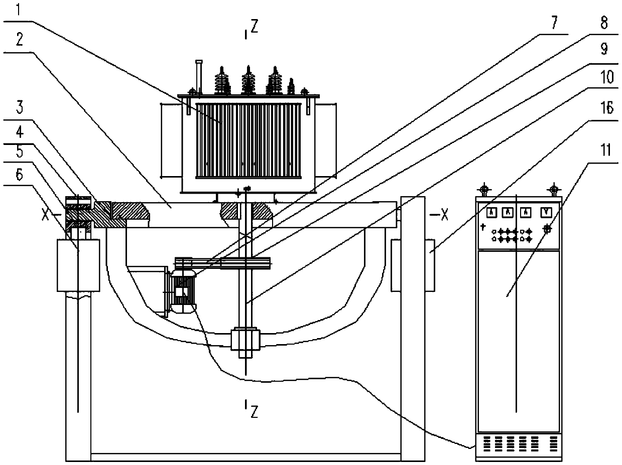
[0036] Fix the transformer 1 with a rated capacity of 4000kVA and below and a weight of 4 tons or below on a circular rotating disk 2 with a diameter of 2500mm. The rotating disk 2 can rotate freely on the circular track of the disk bracket 3, and the speed can be 0-1000 R / M is adjusted, the transmission shaft 10 is rigidly connected to the rotary disc 2 through a key, and the disc bracket 3 is connected to the transmission shaft 10 through a bearing and supports the transmission shaft so that it can rotate; the speed regulating motor 8 is fixed on the chassis , and drive the belt 7 to drive the pulley 9, drive the transmission shaft 10 to rotate, and then the rotating disk 2 and the transmission shaft 10 rotate synchronously. The principle is: the transformer rotates on the rotating disk, and it will bear the impact of centrifugal fo...

Embodiment 2

[0038] In this embodiment, the test bench is used to simulate the impact of the road transport vehicle on the transformer when climbing or descending the slope:

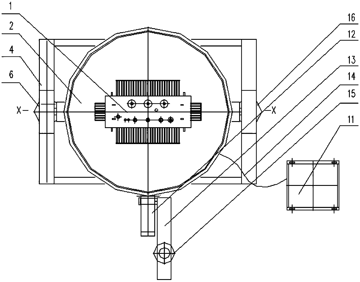
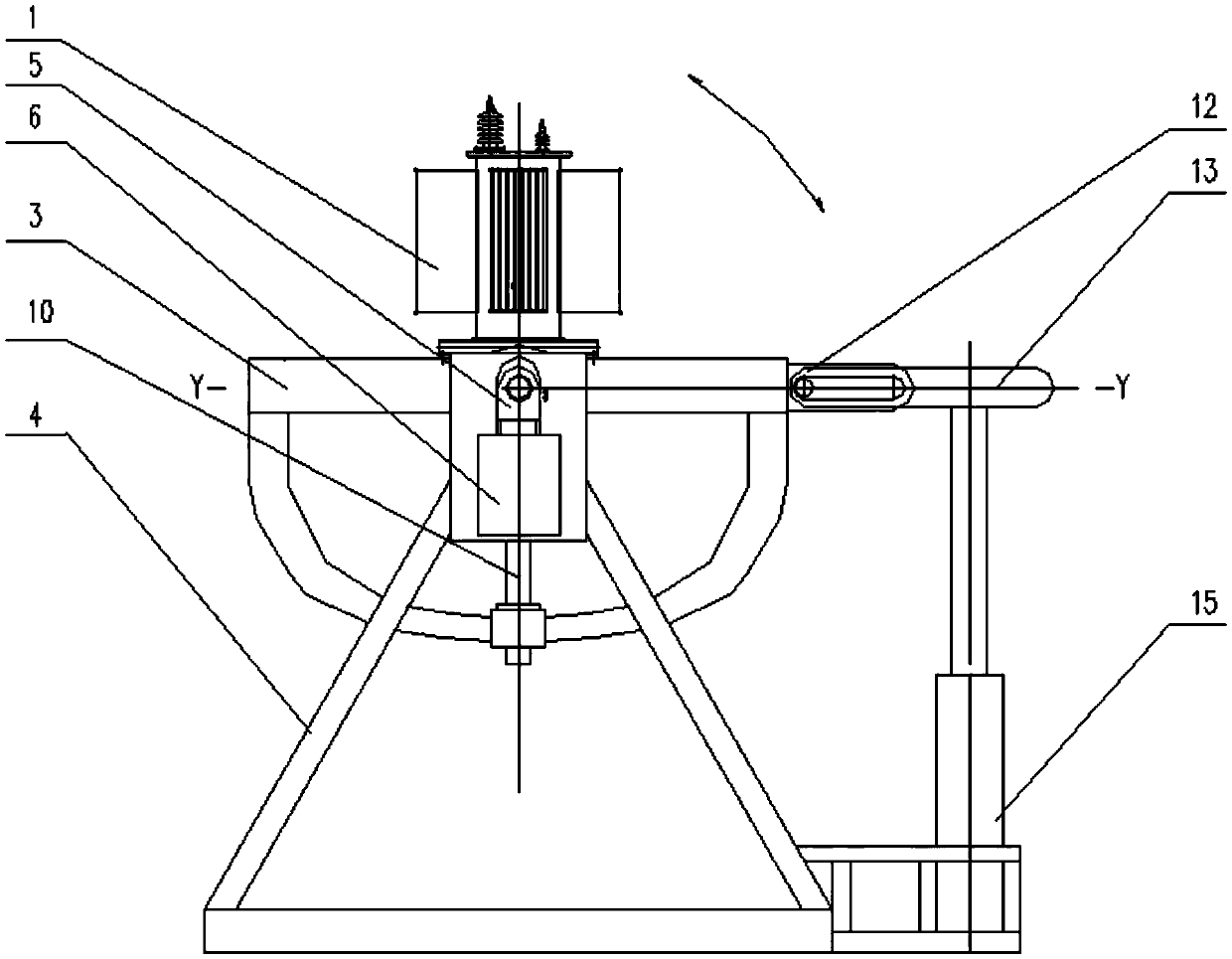
[0039] Driven by a second hydraulic cylinder 15, the disc bracket 3 moves up and down through the round shaft at the front end of the oil cylinder connecting rod 13, and the round shaft will slide in the rotary connection chute 12 of the disc bracket, driving the disc bracket 3 Rotating 20° around the X axis drives the transformer 1 on the table of the rotating disk 2 to tilt 20°. Generally, the maximum gradient of a truck should be 30%, that is, about 16.7°. The principle is: the transformer is tilted 20° on the rotating disk, and it will bear the lateral impact force and inertial force brought by a part of gravity, which can simulate the impact on the transformer when the car climbs and descends the slope.

Embodiment 3

[0041] In this embodiment, the test bench is used to simulate the impact of road transport vehicle bumps on the transformer:

[0042] The round shaft of the disc bracket is installed in the round hole of the slider 5, and the first hydraulic cylinder 6, 16 synchronously drives the slider 5 to reciprocate up and down, the stroke is 25.4mm (1 inch), the frequency is 0-6Hz, and the transformer 1 is driven along the Z The axis moves up and down. The principle is: the up-and-down movement of the stroke and frequency makes the transformer withstand the impact of the up-and-down movement, simulating the impact of the bumps in the transportation process of the car.


PUM


Abstract

The invention relates to a transformer simulative transportation testbed and application thereof. The transformer simulative transportation testbed comprises a support, a rotary device, a swinging device and a sliding device, wherein the rotary device is mounted on the swinging device, and the swinging device is mounted on the support through the sliding device. When the testbed is used, a transformer is fixedly placed on the rotary device and is driven to rotate by the rotary device, when the swinging device works, the whole rotary device swings to enable the transformer to swing, vertical movement of the transformer can be driven through vertical sliding of the sliding device on the support, and through cooperative working of the rotary device, swinging device and sliding device, various transportation conditions of the transformer in the way of transportation can be simulated. A traditional single mode of simulating transportation conditions of a transformer is changed, various transportation modes in a transportation process of the transformer are simulated to be a whole, and the transportation conditions of the transformer can be truly reflected, thereby providing data reference for design of a transformer, and quality reliability of a transformer product can also be verified.

Description

technical field [0001] The invention relates to a transformer simulation transportation test bench and its application, belonging to the technical field of transformers. Background technique [0002] At present, the design of transformer molding has generally been verified by actual operation, and qualified products can be produced by strictly following the process documents during manufacturing. With the continuous development of technology, various models have appeared one after another, such as: S13, SH15, SCB11, SCB13, SCBH15, plus the voltage level of some foreign orders is different from the existing level in our country, all of which require transformer manufacturers to follow different models , voltage, capacity, material (silicon steel sheet, amorphous alloy) structure, etc. are designed. Newly designed products may have no problems after static tests, but after long-distance transportation (including: road, sea), loading and unloading, the transformer will be bump...

Claims


Application Information

Patent Timeline
IPC IPC(8): G01R31/00G01M7/08
CPCG01M7/08G01R31/003
Inventor 王庆保丁保江贾天具
Owner CETC NINGBO MARINE ELECTRONICS RES INST
Why Eureka
Try Eureka