Fly's-eye lens-based laser display shimming shaping device

A fly-eye lens and laser display technology, which is applied in optics, optical components, instruments, etc., can solve the problems of affecting the quality of projected images, affecting image uniformity, and low transmission efficiency, achieving good shimming effect, easy processing and installation, The effect of light field uniformity

Active Publication Date: 2016-04-20
SHANXI OVISION OPTRONICS CO LTD
View PDF4 Cites 10 Cited by
  • Summary
  • Abstract
  • Description
  • Claims
  • Application Information

AI Technical Summary

Problems solved by technology

However, since the X-beam splitter is usually formed by cross-bonding two filters with different wavelengths, the transmission efficiency at the cross position is low. After the central part of the incident light passes through the fly-eye lens and the X-beam splitter, it corresponds to A dark field area is formed on the image surface, which seriously affects the uniformity of the image after being projected onto the screen, and affects the quality of the projected picture

Method used


Image

  • Fly's-eye lens-based laser display shimming shaping device
  • Fly's-eye lens-based laser display shimming shaping device
  • Fly's-eye lens-based laser display shimming shaping device

Examples


Embodiment Construction

[0028] Specific embodiments of the present invention will be described in detail below in conjunction with the accompanying drawings.

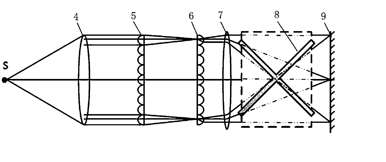
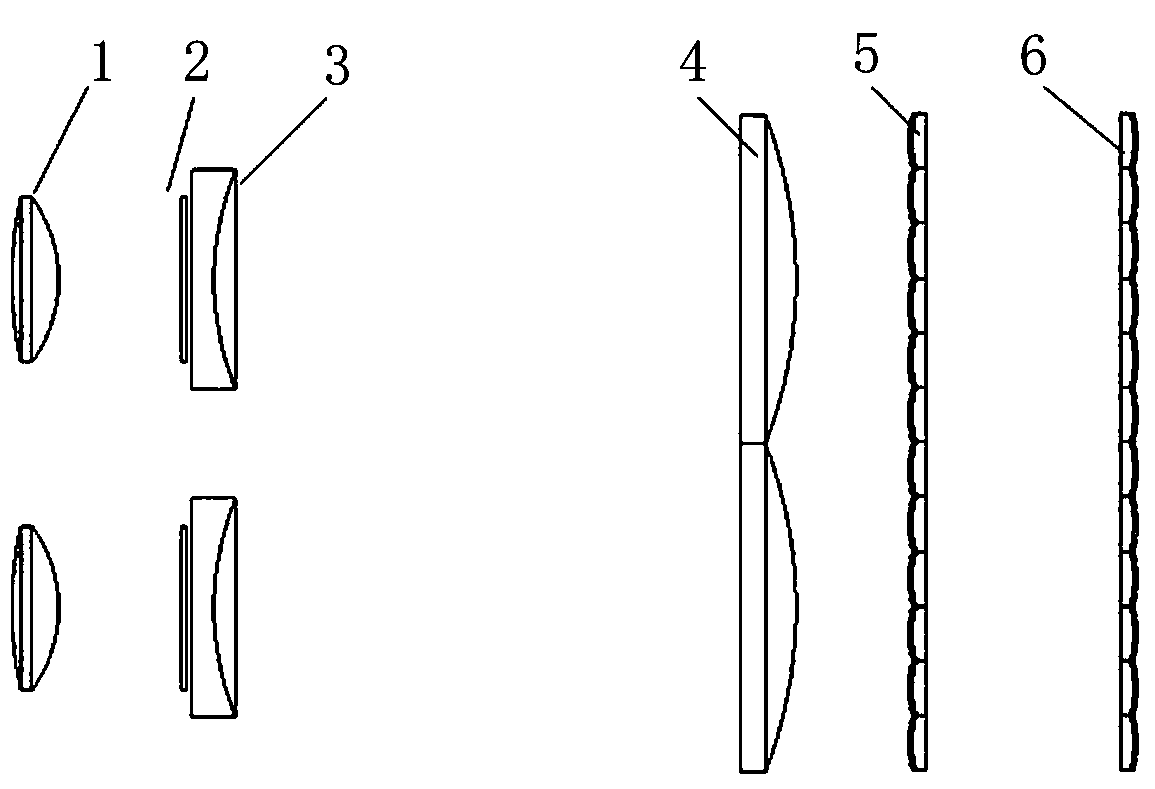
[0029] A laser display shimming device based on a fly-eye lens, such as figure 1 As shown in . The first collimating lens 1 is fixedly connected with the output end of the bundled optical fiber through mechanical parts. The first collimating lens 1, the diffuser 2, the concave lens 3, and the second collimating lens 4 are sequentially fixedly connected through a mechanical structure; the mechanical structure is a fixed structure for fixing optical devices, and can change the distance between the lenses in the optical path to adjust the size of the spot. The transparent diffusion sheet 2 is an existing known structure.

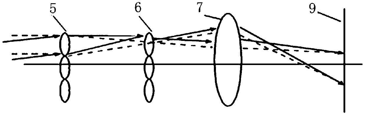
[0030] The incident light sequentially passes through the first collimating lens 1, the diffusion sheet 2, the concave lens 3, and the second collimating lens 4, and then enters the first fly-eye lens 5, and further passes t...


PUM


Abstract

The invention provides a laser beam shimming and speckle inhibiting device. The device comprises a collimating lens, a diffusion sheet, a condenser and a fly's-eye lens. The light dodging effect of the fly's-eye lens is used, the fly's-eye lens is divided into four identical areas, the collimating lens and the diffusion sheet are used to receive, expand and collimate a laser beam, then the laser beam is input to the fly's-eye lens in two rows for light dodging shaping, and later the laser beam is incident to an X light splitter for light splitting projection. According to the structure, the laser beam is reasonably divided into four light paths, and the defect that the X light splitter forms dark stripes at the center of a picture screen in a projection system is reasonably compensated. The device has the advantages of being simple in structure, stable in operation, good in image screen display effect, uniform in light field and the like, and can be applied to the technical field of lighting or displaying by taking coherent light as a light source.

Description

technical field [0001] The invention relates to the technical field of laser display, in particular to optical equipment and instruments applied to laser illumination, laser display, and coherent light as a light source, in particular to a laser display shim shaping device based on a fly-eye lens. Background technique [0002] Laser has the characteristics of high brightness, small wavelength bandwidth, and small etendue, and has broad application prospects in the field of laser display and laser lighting. However, since the laser emits a single-mode or multi-mode Gaussian beam, the light field distribution is not uniform, so it is necessary to convert the laser beam into a beam with a specific shape (such as a rectangle or a square) and uniform intensity. [0003] The fly-eye lens is composed of a series of identical microlenses. The lighting optical system based on the fly-eye lens has the advantages of high light energy utilization rate and simple structure. It has a wide...

Claims


Application Information

Patent Timeline
Patent Type & Authority Applications(China)
IPC IPC(8): G02B27/09
CPCG02B27/0955G02B27/0961
Inventor 高文宏郭泽斌胡元元赵永高
Owner SHANXI OVISION OPTRONICS CO LTD
Why Eureka
Try Eureka