
Evaluation method and evaluation system for feeder automatic processing effect

A technology for feeder automation and processing effects, applied in the electrical field, can solve the problems of live fault range, fault range expansion, and differences in the maintenance section, and achieve the effect of convenient evaluation and comprehensive evaluation results

Inactive Publication Date: 2016-04-20
SHANGHAI JIAO TONG UNIV +3
View PDF0 Cites 7 Cited by
  • Summary
  • Abstract
  • Description
  • Claims
  • Application Information

AI Technical Summary

Problems solved by technology

[0007] 1. The operation of fault handling has strict timing. If the faulty area is not isolated, the recovery operation of the non-faulty area cannot be carried out, otherwise it will lead to the expansion of the fault range and cause the power supply security of the normal line
Therefore, even if the action result state is correct, it cannot guarantee that the action process is safe;
[0008] 2. Only qualitative judgments can be made, and it is impossible to make judgments on the recovery ratio and recovery speed of the feeder automation system to the non-faulty area;
[0009] 3. When the input conditions are not met or the information is incomplete, the final result is often different from the set result, but different solutions provide different help to the final customer, and traditional methods cannot reflect this difference;
[0010] 4. Fault handling results. The above two methods can only judge the power supply recovery process or power supply recovery results, and the evaluation of FA’s action structure is not comprehensive enough. The quality of fault handling is not only related to the size of the power supply area recovery but also to the recovery Speed ​​related;
[0011] 5. In the process of troubleshooting, possible wrong behaviors will lead to electrification in the maintenance section or expansion of the fault range

Method used


Image

  • Evaluation method and evaluation system for feeder automatic processing effect
  • Evaluation method and evaluation system for feeder automatic processing effect
  • Evaluation method and evaluation system for feeder automatic processing effect

Examples


Embodiment Construction

[0046] The technical solutions in the embodiments of the present invention will be clearly and completely described and discussed below in conjunction with the accompanying drawings of the present invention. Obviously, what is described here is only a part of the examples of the present invention, not all examples. Based on the present invention All other embodiments obtained by persons of ordinary skill in the art without creative efforts fall within the protection scope of the present invention.

[0047] In order to facilitate the understanding of the embodiments of the present invention, specific embodiments will be taken as examples for further explanation below in conjunction with the accompanying drawings, and each embodiment does not constitute a limitation to the embodiments of the present invention.

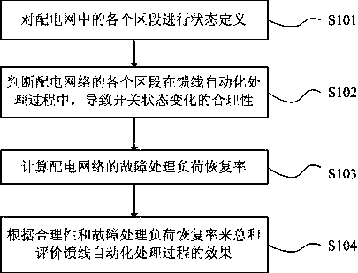
[0048] combine figure 1 , the feeder automatic processing effect evaluation method of the present invention is described in detail, which includes the following steps: ...


PUM


Abstract

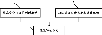
The invention discloses an evaluation method and evaluation system for a feeder automatic processing effect. The method comprises: reasonability of switching state changing at all zones of a distribution network during the feeder automatic processing process is determined; a fault processing load recovery rate of the distribution network is calculated; and according to the reasonability and the fault processing load recovery rate, a feeder automatic processing effect is evaluated comprehensively. In addition, the system is composed of a state changing reasonability determination unit, a fault processing recovery rate calculation unit, and an effect evaluation unit. According to the evaluation method and evaluation system, the feeder automatic processing effect is evaluated comprehensively from the two perspectives of the action process and the action result of the feeder automatic processing, so that the evaluation result can disclose the feeder automatic processing effect accurately and comprehensively.

Description

[0001] This application claims the priority right with the filing date being November 28, 2014, the application number being 201410708536.9, and the name being a feeder automation processing effect evaluation method. technical field [0002] The invention relates to the field of electrical technology, in particular to an evaluation method and evaluation system for feeder automatic processing effects. Background technique [0003] Feeder automation (FA) has many different processing modes, such as centralized master station mode, substation isolation master station recovery mode, intelligent distributed local control mode, current counting local control mode, voltage time local control mode etc.; For a processing mode, different suppliers have different processing strategies and different action processes. Traditionally, two methods are generally used to evaluate the action results of FA: [0004] 1. Check whether the final result is consistent with the set result; [0005]...

Claims


Application Information

Patent Timeline
Patent Type & Authority Applications(China)
IPC IPC(8): G06Q10/00G06Q50/06
CPCG06Q10/00G06Q50/06
Inventor 刘东凌万水朱红张明嵇文路朱红勤
Owner SHANGHAI JIAO TONG UNIV
Learn More