PTZ correction method

A correction method and cloud platform technology, applied in image data processing, instruments, calculations, etc., can solve the problems of increased cost and low correction accuracy, and achieve the effect of improving alignment accuracy and reducing target deviation error

Inactive Publication Date: 2016-04-20
LUOYANG INST OF ELECTRO OPTICAL EQUIP OF AVIC
View PDF9 Cites 45 Cited by
  • Summary
  • Abstract
  • Description
  • Claims
  • Application Information

AI Technical Summary

Problems solved by technology

It can be seen that an external sensor is required in this document, which not only increases the cost, but also may cause low calibration accuracy due to the error of the external sensor itself

Method used


Image

  • PTZ correction method
  • PTZ correction method
  • PTZ correction method

Examples


Embodiment Construction

[0025] The specific embodiments of the present invention will be further described below in conjunction with the accompanying drawings.

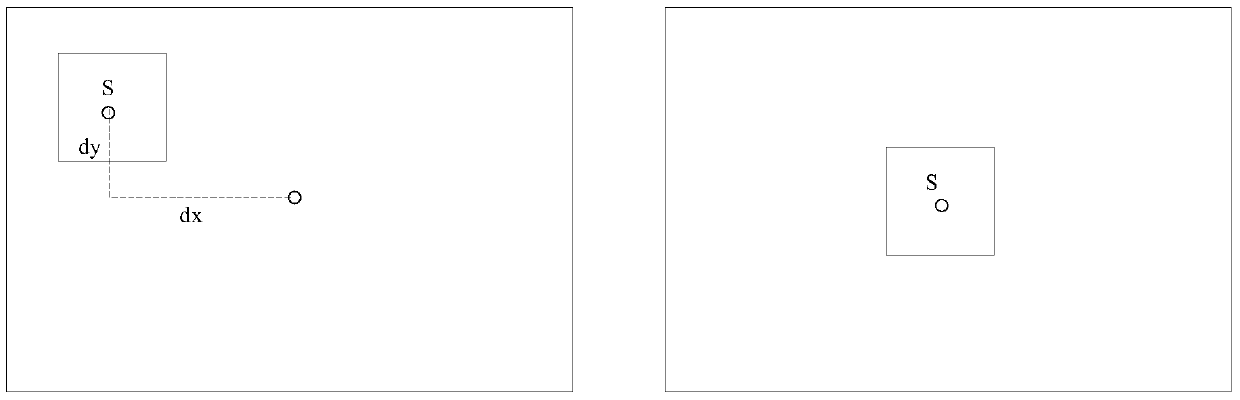
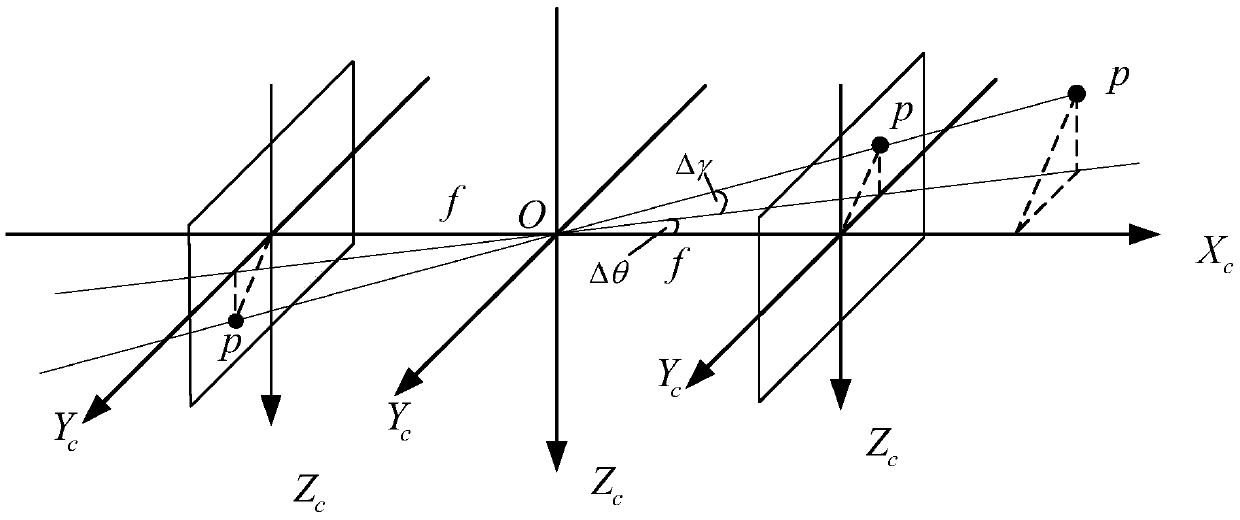
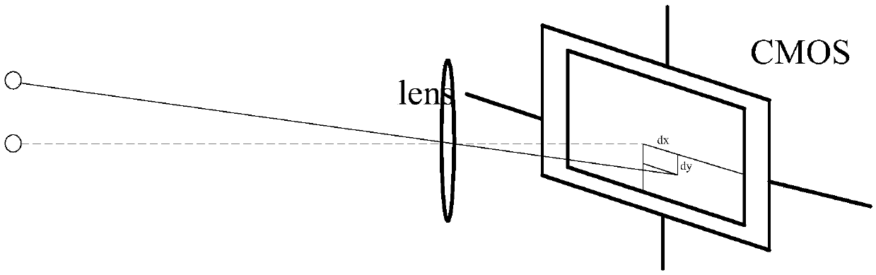
[0026] The present invention uses machine vision technology to identify the target point, by collecting a picture at a certain preset position as a template picture, and recording the azimuth, pitch angle and camera zoom factor at this time; modeling the template picture, using the template The center point of the picture is taken as the center to extract the outline of the target object; set the pan / tilt and camera to collect the picture at the preset position when the template picture is collected, compare the collected picture with the template picture, and calculate the offset pixel of the target object ; Calculate the gimbal offset angle according to the obtained offset pixels, and add the obtained gimbal offset angle to the gimbal preset position to obtain the corrected absolute angle. The following takes the pan-tilt calibration proce...


PUM


Abstract

The present invention relates to a PTZ correction method, belonging to the technical field of PTZ calibration. Firstly, the image of a preset position is collected as a template image, and an azimuth, a pitch angle and a camera zoom ratio at that time are recorded; then the template image is subjected to modeling, and the outline of a target object is extracted with the center point of the template image as a center; then a PTZ and a camera are set to carry out image collection with the preset position of the template image in collection, the collected image and the template image are compared, and the offset pixel of the target object is calculated; and finally the PTZ offset angle is calculated according to the obtained offset pixel, and the PTZ offset angle is added to the PTZ preset position, and a corrected absolute angle is obtained. The machine vision technology is used to identify a target point, the PTZ posture can be quickly adjusted, an external sensor is not needed, the alignment precision of the PTZ is improved, and the target deviation error in shooting the image is reduced.

Description

technical field [0001] The invention relates to a cloud-tilt calibration method, which belongs to the technical field of cloud-tilt calibration. Background technique [0002] In unattended substations, remote monitoring of computer rooms and other places that require mobile monitoring, there are no relevant staff on duty at ordinary times, and the operation and maintenance personnel operate the mobile track cameras in the monitoring place through the remote control of the pan-tilt device in the control center. Carry out daily inspection work. For example, the inspection robot in the substation needs to conduct inspections in the substation. During the inspection process, it needs to stop at a specific point to collect pictures. Due to the navigation accuracy, the parking error of the robot will be too large, causing the deviation of the captured pictures. In order to improve the alignment accuracy of the gimbal, it is necessary to calibrate the gimbal. Most of the traditio...

Claims


Application Information

Patent Timeline
Patent Type & Authority Applications(China)
IPC IPC(8): G06T7/00
CPCG06T2207/30244
Inventor 张风奇
Owner LUOYANG INST OF ELECTRO OPTICAL EQUIP OF AVIC
Why Eureka
Try Eureka