Non-magnetic position detection sensor

A sensor and magnetic frame technology, applied in the field of non-magnetic position detection sensors, can solve the problems of affecting the accuracy and sensitivity of the action, high cost, easy to drop powder, etc., so as to improve the working stability and service life, improve the sensitivity and accuracy The effect of avoiding metal fatigue and impact

Inactive Publication Date: 2016-04-20
FOSHAN YIFU TECH CO LTD +1
View PDF4 Cites 0 Cited by
  • Summary
  • Abstract
  • Description
  • Claims
  • Application Information

AI Technical Summary

Problems solved by technology

[0003] Existing magnetic proximity switches realize position sensing through magnetic field detection, most of which are divided into Hall type, magnetic group type, reed switch type, etc., and the core magnetic sensitive elements are mostly imported from abroad, the production cycle is long and the core Technology is controlled by others, leading to high costs
Most of the existing magnetic sensors rely on the interaction force between internal magnetism and external magnetism to realize the disconnection and connection of the head. The internal magnetism is easy to magnetize the conductive metal structure and affect the accuracy and sensitivity of the action; and the internal magnetism adopts ferrite hard magnetism It is easy to drop powder, and the use of NdFeB hard magnets requires electroplating to coat the magnetic powder. The electroplating layer on the contact part is easy to fall off under long-term repeated actions, resulting in loss of internal magnetic function or magnetic powder falling off and affecting electrical contact.

Method used


Image

  • Non-magnetic position detection sensor
  • Non-magnetic position detection sensor

Examples


Embodiment Construction

[0020] The technical solutions of the present invention will be described below in conjunction with the accompanying drawings and embodiments.

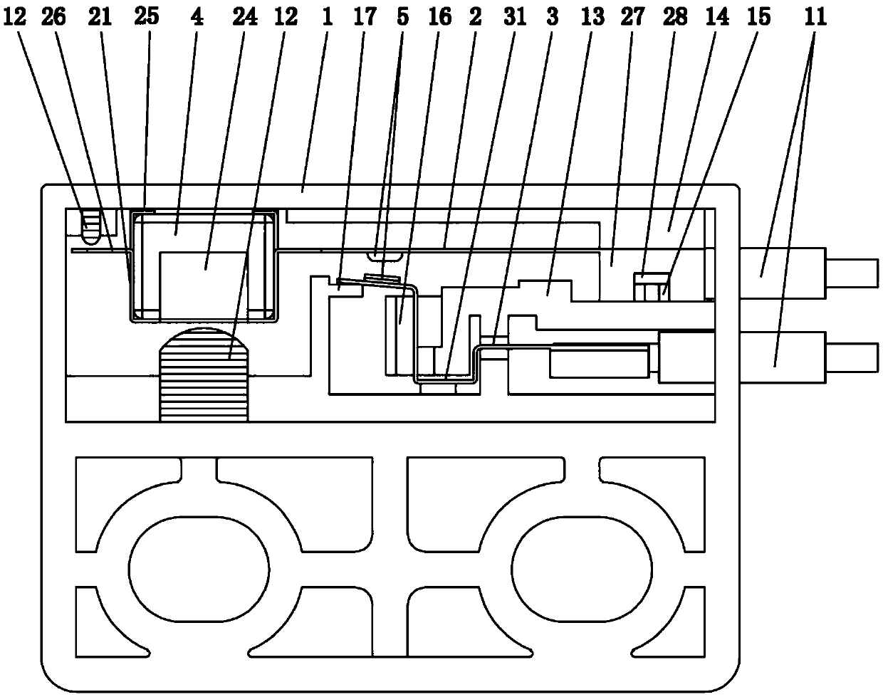
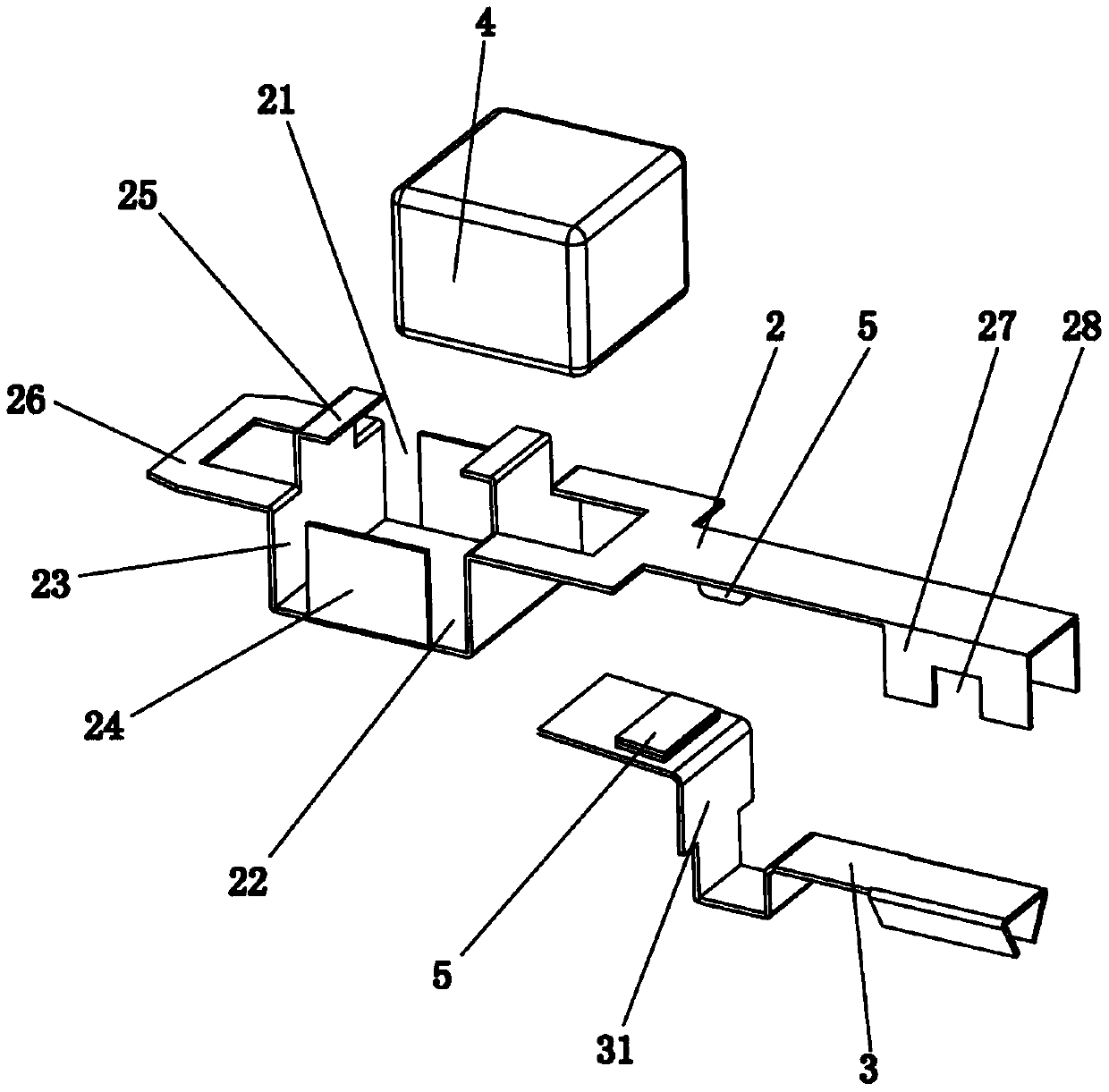
[0021] Such as figure 1 As shown, a non-magnetic position detection sensor according to the present invention includes a hollow plastic box 1, an action piece 2 is arranged horizontally in the inner cavity of the plastic box 1, and one end of the action piece 2 is fixed to the plastic box 1 connection, the action piece 2 is flexible and the other end can move freely up and down, the action piece 2 is provided with a silver contact 5 and a conductive sheet 3 is provided under the silver contact 5 to be on-off with it, and the plastic box 1 On the side wall, there are inlet and outlet leads 11 that are electrically connected to the action piece 2 and the conductive piece 3 respectively; the plastic box 1 is provided with a magnetizable body 4, and the magnetizable body 4 is connected to the other end of the action piece 2 to form an int...


PUM


Abstract

The invention relates to the technical field of magnetic switches, in particular to a non-magnetic position detection sensor. The non-magnetic position detection sensor comprises a hollow plastic box, wherein an operating sheet is transversely arranged in an inner cavity of the plastic box; a silver connection joint is arranged on the operating sheet, and a conductive sheet which is in on-off fit with the silver connection joint is arranged below the silver connection joint; a magnetizer is arranged in the plastic box, and is connected with the other end of the operating sheet to realize integrated linkage setting; a buffering body matched with the magnetizer is arranged in the plastic box below the magnetizer. The non-magnetic position detection sensor is reasonable in structure; external magnetism drives the operating sheet to be matched with the conductive sheet to realize on and off change; by means of shock absorption and reset driving of the buffering body, metal fatigue and impact of the operating sheet can be avoided, so that the working stability of the sensor is improved, and the service life is prolonged; the operating sheet can bear magnetic induction, operation driving and electric connection action; a magnetism fixing frame can realize a magnetism aggregation effect through a magnetic shielding material, so that the sensitivity and the accuracy of position detection are improved; the non-magnetic position detection sensor is simple in whole structure, convenient to process and assemble and high in control precision, and the whole cost of the sensor is reduced.

Description

technical field [0001] The invention relates to the technical field of magnetic switches, in particular to a non-magnetic position detection sensor. Background technique [0002] The magnetic proximity switch is a kind of proximity switch, which can sense the change of the positional relationship through the magnetic element, and convert the non-electric or electromagnetic quantity into the required electrical signal, so as to achieve the purpose of control or measurement. For robot application technology, automatic navigation and position detection are the core technologies to realize intelligent control, and the position detection and execution control scheme provided by the proximity switch has advantages that other controllers do not have. Magnetic proximity switches are used in military fields such as magnetic fuze warheads and spacecraft fluxgates, high-end equipment manufacturing industries such as high-speed trains, automatic elevators, and magnetothermal power gener...

Claims


Application Information

Patent Timeline
Patent Type & Authority Applications(China)
IPC IPC(8): H01H36/00
CPCH01H36/008
Inventor 刘利龙克文
Owner FOSHAN YIFU TECH CO LTD
Why Eureka
Try Eureka