Solar energy controller power source circuit

A solar controller, power circuit technology, applied in battery circuit devices, circuit devices, current collectors, etc., to achieve the effect of prolonging life

Active Publication Date: 2016-04-20
NANJING PUTIAN DATANG INFORMATION ELECTRONICS
View PDF6 Cites 6 Cited by
  • Summary
  • Abstract
  • Description
  • Claims
  • Application Information

AI Technical Summary

Problems solved by technology

[0003] The technical problem to be solved by the present invention is to design a controller that does not consume battery power to solve the existing technical problems

Method used


Image

  • Solar energy controller power source circuit
  • Solar energy controller power source circuit
  • Solar energy controller power source circuit

Examples


Embodiment 1

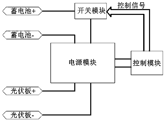
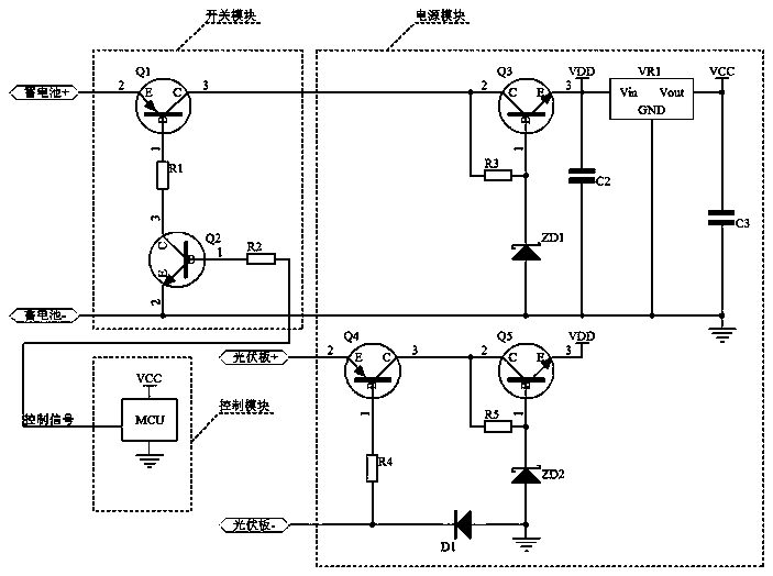
[0029] combine figure 1 and figure 2 , the solar controller power supply circuit of the present invention includes a power supply module, a switch module and a control module, the power supply module is provided with two input sources of photovoltaic panel input and battery input, the battery input is connected to the power supply module through the switch module, and the switch module is connected to the The positive pole of the battery, the switch module is in the disconnected state in the initial state, the power supply module provides working power for the control module, and the control module controls the closing and opening of the switch module. The control module detects the battery voltage value through the voltage detection circuit, and detects the load condition through the no-load judgment circuit. In this embodiment, the control module is an MCU.

[0030] In the initial state, the switch module is in the disconnected state. When there is only battery input, bec...

Embodiment 2

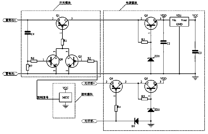
[0045] This embodiment is a schematic diagram of an optimized solar controller power circuit. The difference from Embodiment 1 is that the switch module of the solar controller power circuit of this embodiment also includes a capacitor C4, a resistor R6, a resistor R7 and an NPN transistor Q6 A capacitor C4 and a resistor R7 are connected in series between the positive pole and the negative pole of the battery, the capacitor C4 is connected to the positive pole of the battery, the collector of the NPN transistor Q6 is connected to the collector of the NPN transistor Q2, and the emitter of the NPN transistor Q6 is connected to the negative pole of the battery. One end of the resistor R6 is connected to the base of the NPN transistor Q6, and the other end is connected to one end of the resistor R7 connected to the capacitor C4.

[0046] Since the battery voltage charges the capacitor C4 through the resistor R7, when the capacitor C4 is not fully charged, the end connected to R7 i...

Embodiment 3

[0051] combine figure 1 and Figure 4 , this embodiment is a schematic diagram of an optimized solar controller power supply circuit. The difference from Embodiment 1 is that a voltage regulator is connected between the negative pole of the photovoltaic panel of the power module of the solar controller power supply circuit of this embodiment and resistor R4 Diode ZD3, the negative pole of the Zener diode ZD3 is connected to the resistor R4, and the positive pole of the Zener diode ZD3 is connected to the connection line between the diode D1 and the negative pole of the photovoltaic panel. The advantage of this is that the PNP transistor Q4 can be turned on only when the voltage applied to the photovoltaic panel terminal must be higher than the regulated voltage value of the Zener diode ZD3, which can avoid signal interference and turn it on by mistake, and improve the reliability of the circuit. Other working processes are consistent with those of the circuit in Embodiment 1,...


PUM


Abstract

The invention relates to a solar energy controller power source circuit. The solar energy controller power source circuit includes a power source module, a switch module and a control module; the power source module is provided with two input sources, namely, photovoltaic panel input and storage battery input; the storage battery input is connected with the power source module through the switch module; and under an initial state, the switch module is in a switched-off state, the power source module provides a working power source for the control module, and the control module controls the switching on and switching off of the switch module and detects the voltage value and load condition of a storage battery. A controller adopting the solar energy controller power source circuit of the invention can automatically cut off a connection between the controller and the storage battery when the controller does not work, and the controller can be stored for a long time; when detecting that the storage battery is in a under-voltage state and is short of electrify, the controller will automatically cut off a connection between the controller and the storage battery, and will not consume the power of the storage battery, and therefore, the service life of the storage battery can be effectively prolonged.

Description

technical field [0001] The invention relates to the photovoltaic field, in particular to a solar controller power supply circuit. Background technique [0002] With the development of photovoltaic technology, the use of solar energy has been widely used in various fields. The most common is to use solar panels to charge batteries to convert solar energy into electrical energy and store it with batteries, and then use batteries to provide electricity for other purposes. The device is powered. Among them, the more common types of batteries used for energy storage include lead-acid batteries, gel batteries and lithium-ion batteries. With the development of lithium-ion battery technology, due to its high energy density, compared with lead-acid batteries and gel batteries, it has the advantage of small size under the same capacity, lithium-ion batteries are more and more used in Photovoltaic LED lighting system, and integrate lithium-ion battery and controller, which is called ...

Claims


Application Information

Patent Timeline
Patent Type & Authority Applications(China)
IPC IPC(8): H02J7/35
CPCH02J7/35Y02E10/56
Inventor 王飞闻亚周进马兰
Owner NANJING PUTIAN DATANG INFORMATION ELECTRONICS
Why Eureka
Try Eureka