Electromagnetic heating control device and electromagnetic heating equipment

A heating control device and electromagnetic technology, which is applied in the field of electromagnetic heating equipment and electromagnetic heating control devices, can solve the problems that the induction cooker cannot meet the diverse cooking needs of users, cannot realize voltage zero-crossing, and the power range of the induction cooker is small, etc. Effects of attrition, satisfying cooking needs, and reduced difficulty

Active Publication Date: 2019-04-02
FOSHAN SHUNDE MIDEA ELECTRICAL HEATING APPLIANCES MFG CO LTD +1
View PDF5 Cites 0 Cited by
  • Summary
  • Abstract
  • Description
  • Claims
  • Application Information

AI Technical Summary

Problems solved by technology

[0002] Related single-tube induction cookers are mostly heated by intermittent power adjustment when heating at low power. This is because the IGBT ((Insulated Gate Bipolar Transistor, Insulated Gate Bipolar Transistor) in the single-tube induction cooker cannot achieve voltage zero crossing at about 1000W. Turning on, resulting in a large loss of IGBT, so when the power is lower than 1000W, it can only be heated by intermittent power adjustment
[0003] However, the maximum actual power of a single-tube induction cooker is usually only about 1800W. In this way, the power range for continuous heating in the induction cooker is very small. For example, it can only be heated continuously between 1000W and 1800W.
Some cooking needs continuous low-power or continuous high-power heating to achieve better cooking results, and related induction cookers will not be able to meet the diverse cooking needs of users

Method used


Image

  • Electromagnetic heating control device and electromagnetic heating equipment
  • Electromagnetic heating control device and electromagnetic heating equipment
  • Electromagnetic heating control device and electromagnetic heating equipment

Examples


Embodiment Construction

[0026] Embodiments of the present invention are described in detail below, examples of which are shown in the drawings, wherein the same or similar reference numerals designate the same or similar elements or elements having the same or similar functions throughout. The embodiments described below by referring to the figures are exemplary and are intended to explain the present invention and should not be construed as limiting the present invention.

[0027] The electromagnetic heating control device and the electromagnetic heating equipment proposed according to the embodiments of the present invention are described below with reference to the accompanying drawings.

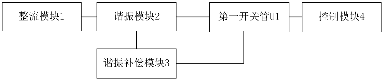
[0028] figure 1 is a schematic block diagram of an electromagnetic heating control device according to an embodiment of the present invention. Such as figure 1 As shown, the electromagnetic heating control device includes: a rectification module 1 , a resonance module 2 , a resonance compensation module 3 , a ...


PUM


Abstract

The invention discloses an electromagnetic heating control device. The electromagnetic heating control device comprises a rectification module used for rectification of an inputted alternating current and outputting a direct current, a resonance module comprising a resonant capacitor and a resonant inductor and used for generating a resonance voltage according to the direct current after rectification, a resonant compensation module connected with the resonant inductor and in parallel connection with the resonant capacitor and used for compensation of capacitance parameters of the resonant capacitor, a first switch tube connected with the resonant compensation module, and a control module used for control of the first switch tube. Thus, when the first switch tube is connected, compensation of capacitance parameters is carried out through the resonant compensation module, the resonance peak voltage is decreased effectively, and the upper limit power of continuous heating is raised. When the first switch tube is disconnected, the fact that the first switch tube can achieve zero voltage connection is ensured, the loss of the first switch tube is reduced, the lower limit power of continuous heating is lowered, and the power scope of continuous heating is widened. The invention also discloses an electromagnetic heating device.

Description

technical field [0001] The invention relates to the technical field of household electrical appliances, in particular to an electromagnetic heating control device and an electromagnetic heating device. Background technique [0002] Related single-tube induction cookers are mostly heated by intermittent power adjustment when heating at low power. This is because the IGBT ((Insulated Gate Bipolar Transistor, Insulated Gate Bipolar Transistor) in the single-tube induction cooker cannot achieve voltage zero crossing at about 1000W. Turning on leads to a large loss of IGBT, so when the power is lower than 1000W, it can only be heated by intermittent power adjustment. [0003] However, the maximum actual power of a single-tube induction cooker is usually only about 1800W, so the power range in which the induction cooker can be continuously heated is very small, for example, it can only be continuously heated between 1000W and 1800W. Some cooking requires continuous low-power or c...

Claims


Application Information

Patent Timeline
Patent Type & Authority Patents(China)
IPC IPC(8): H05B6/06
Inventor 李昌
Owner FOSHAN SHUNDE MIDEA ELECTRICAL HEATING APPLIANCES MFG CO LTD
Why Eureka
Try Eureka