Switch power supply and control method thereof

A technology of switching power supply and control method, applied in the direction of control/regulation system, electrical components, regulating electrical variables, etc., can solve the problems of complex topology structure, existence of circulating current, increased cost, etc., to reduce the number of actions, reduce switching loss, Guaranteed effect of reliability

Active Publication Date: 2014-07-30
HUNAN UNIV +1
View PDF5 Cites 11 Cited by
  • Summary
  • Abstract
  • Description
  • Claims
  • Application Information

AI Technical Summary

Problems solved by technology

In order to achieve zero-voltage turn-on of the switch and zero-current turn-off at the same time, some literature proposes to use a secondary side energy recovery buffer circuit to reset the primary side current. The circuit structure is simple and has high engineering application value. However, the transformer needs to be The special design adds extra cost; there are also literatures that propose a full-bridge phase-shift pulse-width modulation DC / DC converter suitable for high-power arc welding, which introduces additional transformers and additional buffer circuits, which can realize the main work Zero-voltage turn-on and zero-current turn-off under no-load and short-circuit conditions, its topology is complex, and there is a circulating current

Method used


Image

  • Switch power supply and control method thereof
  • Switch power supply and control method thereof
  • Switch power supply and control method thereof

Examples


Embodiment Construction

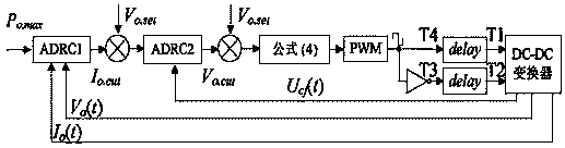
[0039] figure 1 A schematic diagram of a high-efficiency switching power supply topology proposed by the present invention, wherein the front stage is a three-phase voltage type PWM rectifier, and the L in the latter stage DC / DC aux1 , L aux2 is the additional inductance; L seq is the series equivalent inductance; L f 、C f are the output filter inductor and filter capacitor respectively; C s0 is the junction capacitance or shunt capacitance of the IGBT. figure 1 Only two inductive elements L are introduced into the switching power supply structure shown aux1 , L aux2 , the voltage and current of each link that needs to be analyzed in the figure are marked in the figure.

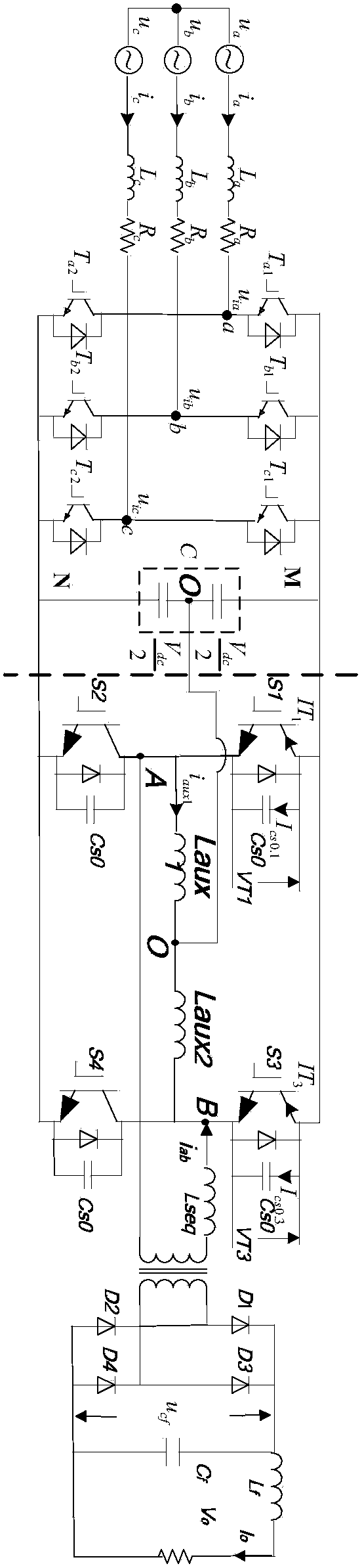
[0040] figure 2 It is an exploded schematic diagram of a switch state of a DC / DC converter according to an embodiment of the present invention.

[0041] image 3 It is a schematic diagram of the ideal state waveform of each link of the DC / DC converter in an embodiment of the present invention, im...


PUM


Abstract

The invention discloses a switch power supply and a control method of the switch power supply. The switch power supply is composed of a three-phase voltage type PWM rectifier and an H-bridge high-frequency DC / DC converter. Two additional inductance elements are introduced to the connecting middle point of a direct-current capacitor and the connecting middle point of a DC / DC converter bridge arm. The introduced additional inductance elements can provide an energy way for the transient state process of an electronic power switch of the DC / DC converter, and therefore the zero voltage switching-on and zero current switching-off of the electronic power switch are achieved. The active-disturbance-rejection control technology is adopted, and therefore stable control over the DC / DC converter can be effectively achieved, the number of switching-on and switching-off actions in the transient state process is lowered, and switching loss is reduced. By means of the switch power supply and the control method, the zero voltage switching-on and zero current switching-off of a lag bridge arm and the zero voltage switching-on and approximate zero current switching-off of an ahead bridge arm can be effectively and simultaneously achieved for the DC / DC converter under various load states, switching loss is reduced, and efficiency of the switch power supply is further improved.

Description

technical field [0001] The invention relates to the technical field of power electronics, in particular to a switching power supply and a control method thereof. Background technique [0002] With the development of power electronic devices, device topology and control technology, modern power electronic technology has become an important means and key factor for high efficiency, energy saving, traditional equipment transformation and industrial upgrading. In recent years, high-efficiency high-frequency switching power supplies for low-voltage fields have been developed successively at home and abroad. Switching power supply is a kind of power supply that uses modern power electronic technology to control the time ratio of semiconductor switching devices to turn on and off, and maintains a stable output voltage and current. Switching power supply is generally composed of a main circuit and a control circuit. The traditional electroplating electrolytic DC power supply mainly...

Claims


Application Information

Patent Timeline
Patent Type & Authority Applications(China)
IPC IPC(8): H02M7/219H02M3/335
Inventor 罗安金国彬王皓陈燕东肖华根
Owner HUNAN UNIV
Why Eureka
Try Eureka