Cutting tool

A cutting tool and tool technology, applied in the manufacture of tools, drilling accessories, turning equipment, etc., can solve the problems of difficult to ensure wall thickness and tool rigidity, and achieve good workability, improved loading and unloading operability and eccentric adjustment Accuracy and improved workability

Inactive Publication Date: 2016-04-20
MITSUBISHI MATERIALS CORP
View PDF9 Cites 6 Cited by
  • Summary
  • Abstract
  • Description
  • Claims
  • Application Information

AI Technical Summary

Problems solved by technology

[0011] However, when a hydraulic chuck structure is simply used for a cutting tool such as the above-mentioned valve dresser, the radial outer side of the chuck cylinder is thin, and the rigidity of the tool cannot be ensured.
[0012] Specifically, in recent years, the diameter of the valve seat of the workpiece material has been required to be further reduced. Therefore, it is difficult to secure a sufficient wall thickness on the radially outer side of the chuck cylinder.

Method used


Image

  • Cutting tool
  • Cutting tool
  • Cutting tool

Examples


Embodiment Construction

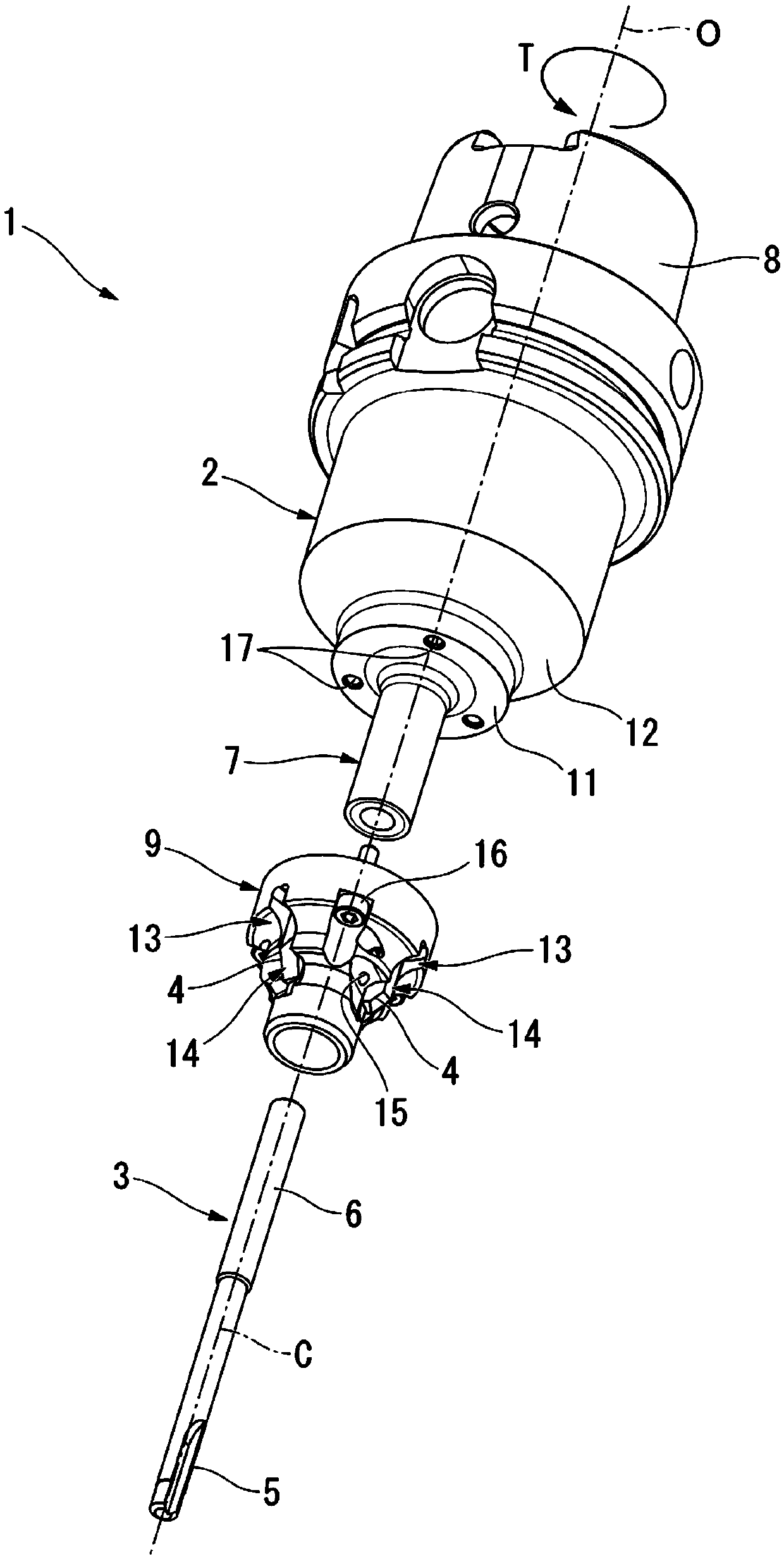
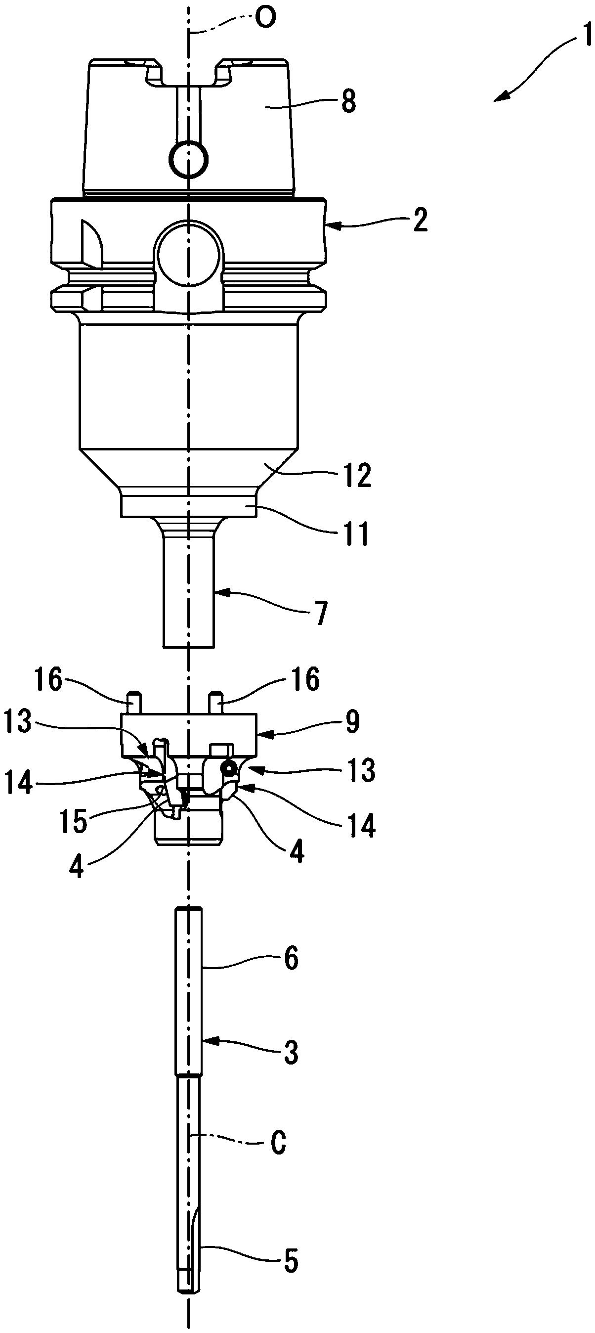
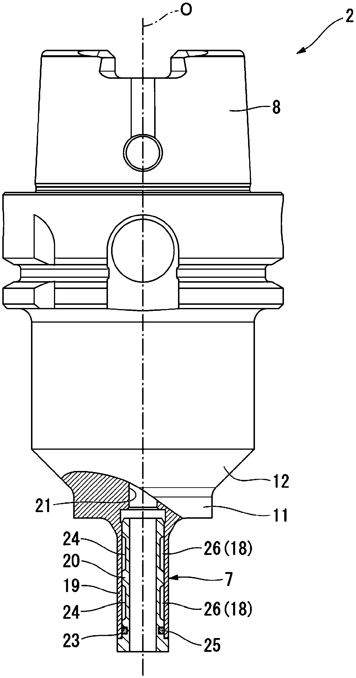
[0042] Hereinafter, a cutting tool 1 according to an embodiment of the present invention will be described with reference to the drawings.

[0043] The cutting tool 1 according to the present embodiment performs hole machining on a workpiece material with a reamer (hole machining tool) 3 extending along the axis O of the tool body 2, and a pair of cutting edges 4 provided on the outer periphery of the front end portion of the head 9. The opening of the machining hole of the workpiece material to be machined is cut. A so-called valve dresser, which is an example of such a cutting tool, performs finishing machining of a valve stem guide hole and machining of a valve seat in a cylinder head of a four-stroke engine coaxially in the same cutting process.

[0044] Such as Figure 1 to Figure 4 As shown, this cutting tool 1 has: a reamer 3 as a shaft-shaped hole machining tool extending along a central axis C; a tool body 2 that rotates around an axis O; and a cylindrical head 9 tha...


PUM


Abstract

This cutting tool (1) is provided with: a tool body (2) that rotates around an axis (O); a cylindrical part (7) provided at the tip on the distal side in the axis (O) direction of the tool body (2) and extending in the axis (O) direction; a boring tool (3) describing the shape of a shaft, detachably fitted on the radial-direction inner side of the cylindrical part (7) and extending so as to project from the cylindrical part (7) toward the distal side; and a head part (9) describing a cylindrical shape, fitted on the radial-direction outer side of the cylindrical part (7), and provided on the outer peripheral section thereof with a cutting blade. The peripheral wall of the cylindrical part (7) is provided with an outer wall (19), an inner wall (20), and a fluid chamber (18) defined between the outer wall (19) and the inner wall (20), the interior of the fluid chamber being filled with fluid. The pressure of the fluid in the fluid chamber (18) is increased, whereby the outer wall (19) elastically deforms toward the radially outward side and presses against the head part (9), and the inner wall (20) elastically deforms toward the radially inward side and presses against the boring tool (3).

Description

technical field [0001] The present invention relates to a cutting tool for forming a machined hole by cutting the inner wall surface of a bottom hole provided in advance in a workpiece material, and cutting the periphery of the opening of the machined hole into a coaxial. [0002] This application claims priority based on Patent Application No. 2013-190963 for which it applied in Japan on September 13, 2013, and uses the content here. Background technique [0003] Conventionally, there is known a cutting tool that performs hole machining of a workpiece material by a reamer (hole machining tool) extending along the axis of the tool body, and that the machined hole is processed by a cutting edge provided on the outer periphery of the front end portion of the tool body. The opening of the machining hole of the workpiece material is cut. A so-called valve finisher (Valve finisher), which is an example of such a cutting tool, performs coaxial finishing of a valve stem guide hol...

Claims


Application Information

Patent Timeline
Patent Type & Authority Applications(China)
IPC IPC(8): B23B31/117B23B41/00B23B41/12B23B51/08B23B51/10
CPCB23B31/305B23B31/40B23B51/107B23C3/055B23B2231/24
Inventor 金星彰熊切孝之
Owner MITSUBISHI MATERIALS CORP
Why Eureka
Try Eureka