Spiral pull-up type broaching machine

A screw and bed technology, applied in the direction of broaching machine, broaching machine device, accessories of broaching machine, etc., can solve the problems of low production efficiency, slow broaching speed, large size of the main slide, etc., to improve work efficiency, The effect of reducing manufacturing cost and ensuring broaching accuracy

Active Publication Date: 2016-04-27
浙江成春自动化设备有限公司
View PDF8 Cites 9 Cited by
  • Summary
  • Abstract
  • Description
  • Claims
  • Application Information

AI Technical Summary

Problems solved by technology

In order to ensure the processing accuracy of parts, such vertical internal broaching machines usually have a larger size of the main slide, especially in the vertical internal broaching machine structure in which the main slide is driven by two oil cylinders, in order to ensure the synchronization of the two cylinders, the main slide The plate is made very long, which leads to the disadvantages of difficult processing of the main slide plate and high manufacturing cost; and in the broaching process of the hydraulic drive mechanism, the broaching speed is slow, the production efficiency is low, it is not environmentally friendly, and it occupies a large area
[0003] At the same time, during the broaching process of the broach, iron filings will be stuck on the broach, which affects the quality of the product

Method used


Image

  • Spiral pull-up type broaching machine
  • Spiral pull-up type broaching machine
  • Spiral pull-up type broaching machine

Examples


Embodiment Construction

[0025] The present invention will be further described below with specific embodiments in conjunction with the drawings:

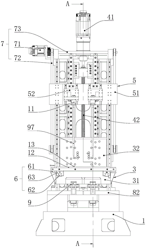
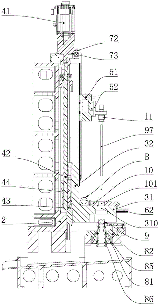
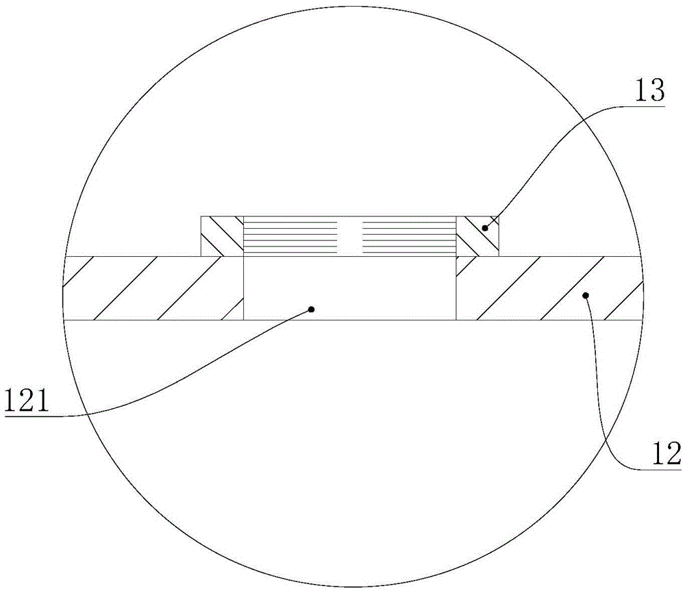
[0026] See Figure 1 to Figure 8 As shown, a spiral pull-up broaching machine includes a base 1, a bed 2 vertically fixed on the base 1, and a slide 3 fixed on the bed 2 and moving up and down along the bed 2, which drives the slide The driving mechanism 4 for the up and down movement of the plate 3, and the worktable 10 arranged on the sliding plate 3 and moving up and down with the sliding plate 3, the knife carrying mechanism 5 and the broach 97 located above the working table 10, the worktable The base 1 below 10 is provided with a lower chuck body 9 for fixing the bottom of the broach 97 and a power mechanism 8 for driving the lower chuck body 9 to rotate. The slide plate 3 is provided with a driving table 10 along the bed 2 The drive assembly 6 reciprocates back and forth. The inner wall of the workbench 10 is provided with a brush mounting plate 12, a...


PUM


Abstract

The invention belongs to the technical field of machinery, and relates to a metal cutting machine tool, in particular to a spiral pull-up type broaching machine. The spiral pull-up type broaching machine comprises a base, a machine body, a slide carriage, a first driving mechanism, a working table, a knife lifting and feeding mechanism and a broach, wherein the machine body is vertically fixed on the base; the slide carriage is fixed on the machine body and moves in the up-down direction along the machine body; the first driving mechanism drives the slide carriage to move in the up-down direction; the working table is arranged on the slide carriage and moves in the up-down direction along with the slide carriage; the knife lifting and feeding mechanism and the broach are positioned above the working table; a lower chuck body for fixing the bottom of the broach and a power mechanism for driving the lower chuck body to rotate are arranged on the base and positioned below the working table; a driving assembly which drives the working table to move in the front-back direction in a reciprocating manner along the machine body is arranged on the slide carriage; a brush mounting plate is arranged on the inner wall of the working table; and a brush which is used for cleaning the broach is arranged on the brush mounting plate. The invention aims to provide the spiral pull-up type broaching machine which is good in structure optimization, high in work efficiency and low in manufacturing cost, and can improve quality of products.

Description

Technical field [0001] The invention belongs to the technical field of machinery, and relates to a metal cutting machine tool, in particular to a spiral pull-up broaching machine. Background technique [0002] With the rapid development and improvement of the manufacturing level of transmission parts in my country's machinery manufacturing industry and the rapid progress in control technology, my country's machine tool manufacturing industry has also achieved rapid development, but as an important member of the machine tool series, broaching machines are still at six. At the level of the 1970s, traditional hydraulically driven broaching machines accounted for almost all of the broaching machine market. The current vertical internal broaching machine usually includes a base, a bed on the base, a slide, and a hydraulic drive mechanism. The hydraulic drive mechanism drives the main slide to move up and down, and then uses the broach on the main slide Broach the workpiece. For examp...

Claims


Application Information

Patent Timeline
Patent Type & Authority Applications(China)
IPC IPC(8): B23Q11/00B23D37/08B23D41/06B23D41/02B23D39/00
CPCB23D37/08B23D39/00B23D41/02B23D41/06B23Q11/0042
Inventor 尤春银薛亚东刘征张国庆江斌
Owner 浙江成春自动化设备有限公司
Why Eureka
Try Eureka