Oxygen-enriched membrane oxygen generation device

An oxygen-generating device and an oxygen-enriched membrane technology, which are applied in the fields of oxygen preparation, oxygen/ozone/oxide/hydroxide, inorganic chemistry, etc., can solve the problems of inability to supply high-concentration oxygen for a long time, high maintenance and replacement costs, and Oxygen results and other problems, to achieve the effect of easy replacement, reduce manufacturing cost and use cost, and improve user experience

Active Publication Date: 2016-04-27
SHANGHAI UNIV OF ENG SCI
View PDF4 Cites 1 Cited by
  • Summary
  • Abstract
  • Description
  • Claims
  • Application Information

AI Technical Summary

Problems solved by technology

[0003] At present, there are many devices in the industry that use oxygen-enriched membranes to produce oxygen using the above principles, but usually cannot solve the following two problems well:
[0004] One is that the remaining nitrogen-enriched air after oxygen production cannot be discharged from the oxygen production device in a timely and effective manner, causing the nitrogen-enriched air to stagnate in the device and mix with the fresh air that enters the device later, reducing the efficiency of the oxygen-enriched membrane oxygen production device. The oxygen content of the air in the air will affect the oxygen production effect of the device in long-term use, so that the oxygen-enriched membrane oxygen production device cannot supply high-concentration oxygen for a

Method used


Image

  • Oxygen-enriched membrane oxygen generation device
  • Oxygen-enriched membrane oxygen generation device
  • Oxygen-enriched membrane oxygen generation device

Examples


Example Embodiment

[0037] The present invention will be further elaborated below in conjunction with specific drawings and embodiments.

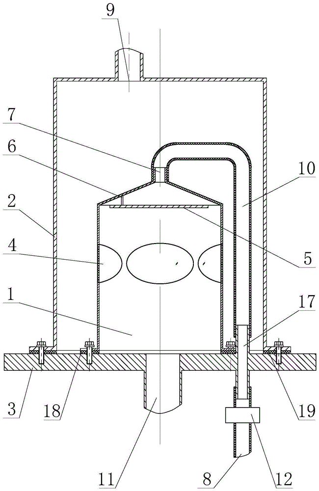
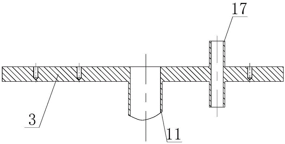
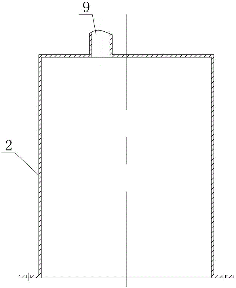
[0038] like figure 1 As shown, the device includes an inner cabin body 1 and an outer cabin body 2 housed inside and outside, and a cabin body seat 3 that is sealed and covered inside, and the bottom openings of the cabin body 1 and the outer cabin body 2 in the outer cabin body. Both the inner cabin body 1 and the outer cabin body 2 are in the shape of a reversed barrel, and the edge of the barrel mouth is turned outwards to form a circle of turned edges. Sealing washer 19, the second sealing washer 18 is arranged between the turned edge of the inner cabin body 1 and the cabin body seat 3, and is locked with bolts respectively. It not only has good sealing performance, but also facilitates disassembly and assembly of the device, internal cleaning and maintenance, and replacement of the oxygen-enriched membrane.

[0039] The cabin seat 3 inside the inner cabin...


PUM


Abstract

An oxygen-enriched membrane oxygen generation device comprises a inner cabin body and an outer cabin body which are nested inside and outside as well as a cabin seat covering openings in the bottoms of the cabin bodies in a sealing manner, wherein both the inner cabin body and the outer cabin body adopt a reversely-buckled barrel shape; an air feeding port is formed in the cabin seat on the inner side of the inner cabin body, a first nitrogen-rich gas exhaust port is formed in the top of the inner cabin body, a gas flow baffle is configured in the inner cabin body, multiple oxygen permeation windows are densely formed in the side wall, and oxygen-enriched membranes are airtightly mounted on the oxygen permeation windows; an oxygen-enriched gas output port is formed in the top of the outer cabin body, and a second oxygen-enriched gas exhaust port is formed in the cabin seat and between the outer cabin body and the inner cabin body; an exhaust end of the first nitrogen-rich gas exhaust port and a gas inlet end of the second nitrogen-rich gas exhaust port are connected through a flexible first exhaust pipe, and a second exhaust pipe provided with a gas flow control valve is configured at the exhaust end of the second nitrogen-rich gas exhaust port. According to the device, the modular and small-size oxygen-enriched membranes are easy to replace by a user; the gas flow baffle can prevent nitrogen from enriching in the side wall area of the inner cabin body, and the oxygen preparation effect in the long-time use process is guaranteed.

Description

technical field [0001] The invention relates to an oxygen-enriched membrane oxygen generator, which belongs to the field of oxygen generators. Background technique [0002] Oxygen production by oxygen-enriched membrane is a common method of physical oxygen production. Its principle is to use the characteristic of polymer oxygen-enriched membrane to allow oxygen molecules in the air to pass through preferentially, filter nitrogen molecules in the air, and achieve concentrated concentration of oxygen in the air. purpose for users. The concentration of oxygen output by the oxygen-enriched membrane oxygen production can reach 30%, which has the advantages of small size and low power consumption, and can be used for simple low-concentration oxygen therapy or home use. [0003] At present, there are many devices in the industry that use oxygen-enriched membranes to produce oxygen using the above principles, but usually cannot solve the following two problems well: [0004] One i...

Claims


Application Information

Patent Timeline
IPC IPC(8): C01B13/02
CPCC01B13/0251C01B2210/0028
Inventor 刘书华张福乐薛亚静
Owner SHANGHAI UNIV OF ENG SCI
Why Eureka
Try Eureka