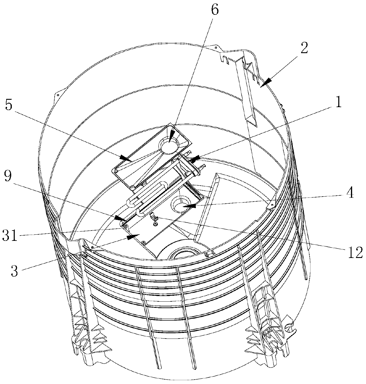
A pulsator washing machine with heating function
A pulsator washing machine, functional technology, applied in the field of washing machines, can solve the problems of drainage cannot be discharged together with water, easy deformation, low heating efficiency, etc., to achieve the effect of reducing bacterial growth, preventing deformation and extrusion, and protecting the heater
- Summary
- Abstract
- Description
- Claims
- Application Information
AI Technical Summary
Problems solved by technology
Method used
Image
Examples
Embodiment 1
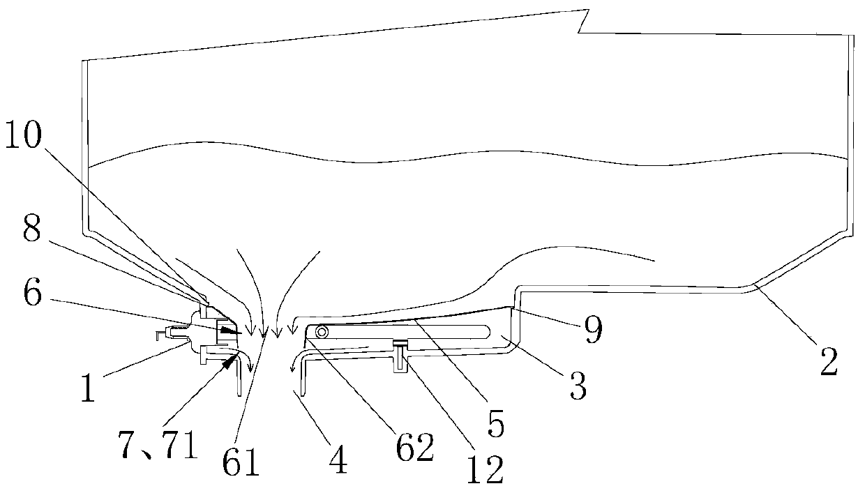
[0030] Such as figure 2 As shown, the cover plate 5 described in this embodiment is sealed and installed in the accommodating tank 3, and only the water-conducting structure 6 is provided with a water passage part 7 so that the upper and lower spaces of the cover plate 5 and the water outlet 4 are all connected. The periphery of the plate 5 and the accommodating groove 3 are sealed by a sealing strip 8 . When the washing machine is fed with water, the water in the outer tub 2 enters the heating space below the cover plate 5 through the water passage 7; when washing, the pulsator or the inner tub agitate the water flow so that the water flow above the cover plate fluctuates greatly, while Because the heating space is relatively sealed, the fluidity of the water flow inside the space is small, and the lint will basically not enter the heating space with the water flow; when draining, the water in the outer barrel 2 is discharged by the water guide structure 6 and the water outl...
Embodiment 2
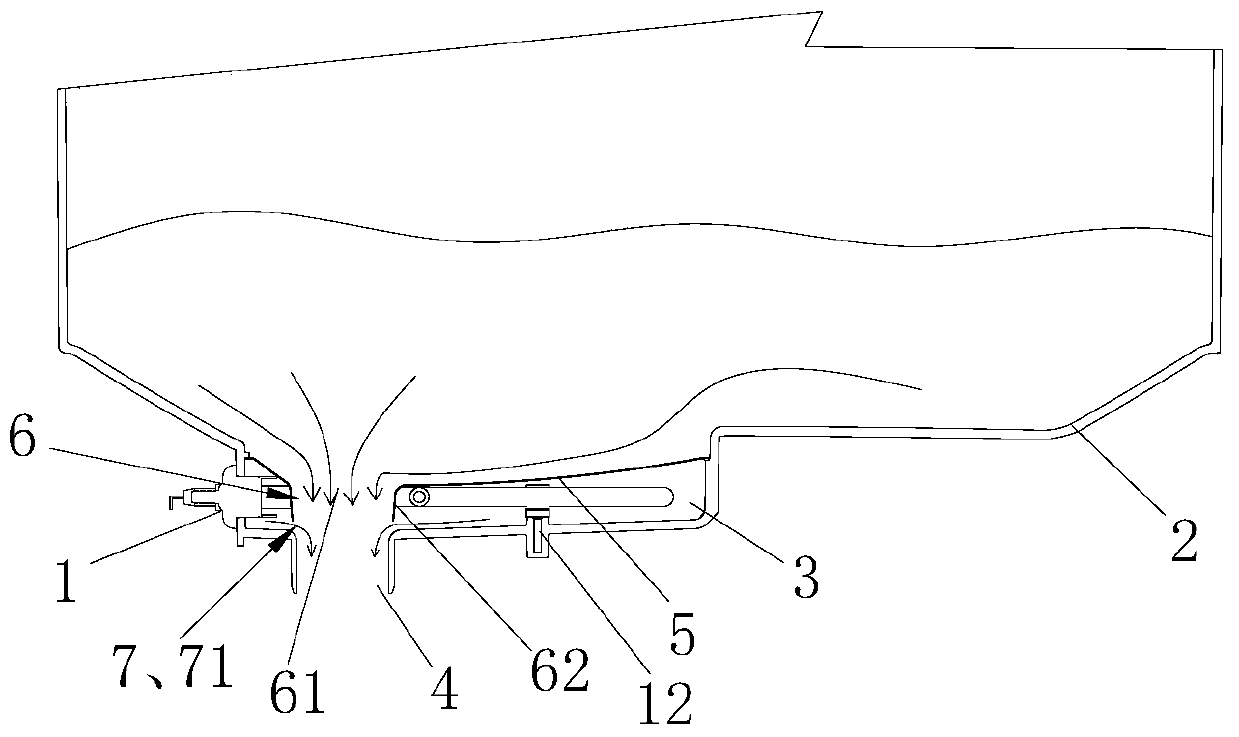
[0032] Such as image 3 As shown, the difference between this embodiment and the first embodiment is that the periphery of the cover plate 5 and the accommodation groove 3 do not require sealing, and the cover plate 5 is directly installed in the opening of the accommodation groove 3, lower than the accommodation groove 3. 3. The upper surface of the outer barrel bottom around the opening. When the washing machine is filled with water, the water in the outer tub 2 enters into the heating space below the cover plate 5 through the unsealed gap around the water passage 7 and the cover plate 5; Small, and the lint will basically not enter the heating space with the water flow; when draining, the flow of the outer barrel 2 from the gap into the water through the heating space is much smaller than the flow of water from the water guide structure 6, and seldom lint flows into the heating space. In the heating space, the speed of lint accumulation in the heating space is much lower t...
Embodiment 3
[0034] Such as Figure 2 to Figure 4 As shown, the water guide structure 6 of the cover plate 5 of the present invention includes a water guide port 61 and a water guide channel 62 communicated with the drain port 4 formed by flanging down around the water guide port 61, and the lower end of the water guide channel 62 is connected to the drain port. There is a gap between the 4, and the gap forms a water outlet 71 that communicates with the top and bottom of the cover plate 5 and the drain port 4.
[0035] Specifically, the lower end of the water guide channel 62 is arranged above the drain outlet 4, and there is a gap between the bottom wall of the accommodation tank 3 around the drain outlet 4 to form the water guide channel 71; or, the lower end of the water guide channel 62 If it extends into the water outlet 4 and is not sealed with the water outlet 4, the water outlet 71 can also be formed.
PUM
 Abstract
Description
Claims
Application Information
 - R&D
- Intellectual Property
- Life Sciences
- Materials
- Tech Scout
- Unparalleled Data Quality
- Higher Quality Content
- 60% Fewer Hallucinations
Browse by: Latest US Patents, China's latest patents, Technical Efficacy Thesaurus, Application Domain, Technology Topic, Popular Technical Reports.
© 2025 PatSnap. All rights reserved.Legal|Privacy policy|Modern Slavery Act Transparency Statement|Sitemap|About US| Contact US: help@patsnap.com


