A spin-floating entrainment metallurgical process and its reactor

A technology of reactor and process, which is applied in the field of spin-floating entrainment metallurgy process and its reactor, can solve the problems of flue gas fluctuation, fall into the bottom of the furnace before reaction, resonance, etc., and achieve the effect of high probability of combined growth

Active Publication Date: 2011-12-07
YANGGU XIANGGUANG COPPER
View PDF10 Cites 23 Cited by
  • Summary
  • Abstract
  • Description
  • Claims
  • Application Information

AI Technical Summary

Problems solved by technology

[0006] According to the inventive process, a gas-solid two-phase mixture can also be formed, but to maintain the gas-solid two-phase mixture in the reaction furnace, a high rotational speed is required, and the high-speed rotating gas-solid two-phase mixture has a strong impact on the nozzle and the swirling flow. The wear of the nozzle is very serious, and the nozzle will not work properly in a short period of time
Introduce pulsating oxygen or oxygen-enriched air into the center of the swirling fluid. From the cross-section of the swirling fluid, the vortex core is actually a cavity with no material or little material; and the introduction of oxygen or oxygen-enriched air in the form of pulsation will cause the central material If the falling speed is too fast, it will fall into the bottom of the furnace before it can react in time; the change of central oxygen potential will inevitably cause the change of reaction time and space, which can increase the collision probability of particles, but it will also cause flue e.g. resonance of a waste heat boiler
The material has formed a gas-solid two-phase mixture before entering the reaction furnace, and the material particles can only be heated by the high-temperature radiation in the furnace, and the time to be heated to the ignition point is too long

Method used


Image

  • A spin-floating entrainment metallurgical process and its reactor
  • A spin-floating entrainment metallurgical process and its reactor
  • A spin-floating entrainment metallurgical process and its reactor

Examples


Embodiment Construction

[0048] The present invention will be further described below in conjunction with the accompanying drawings and embodiments.

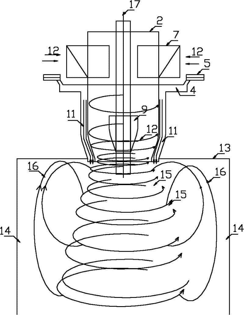
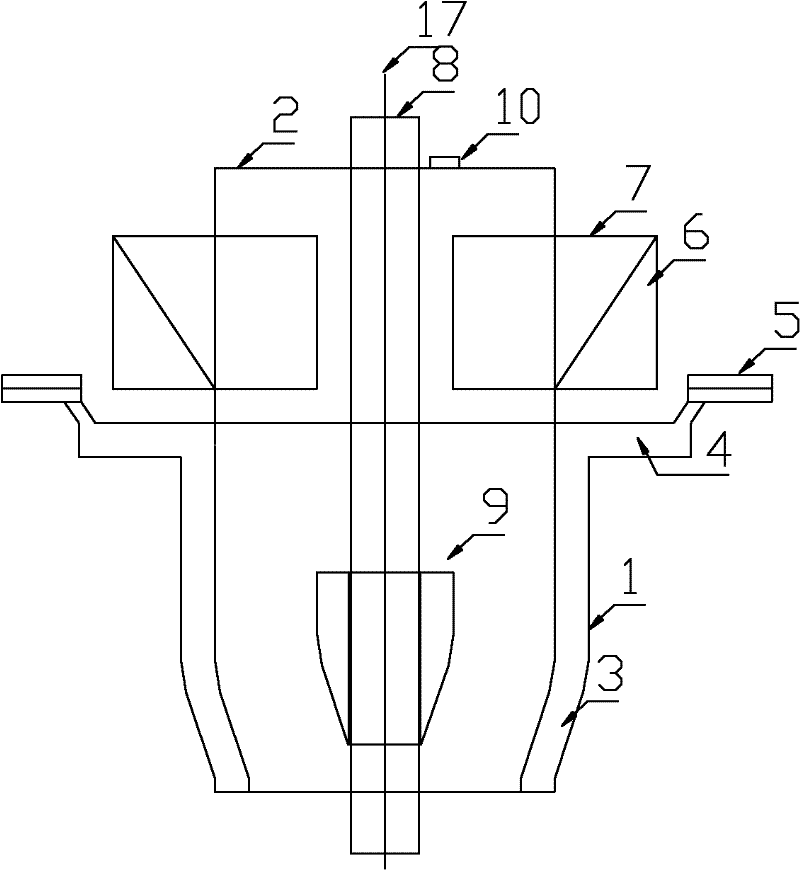
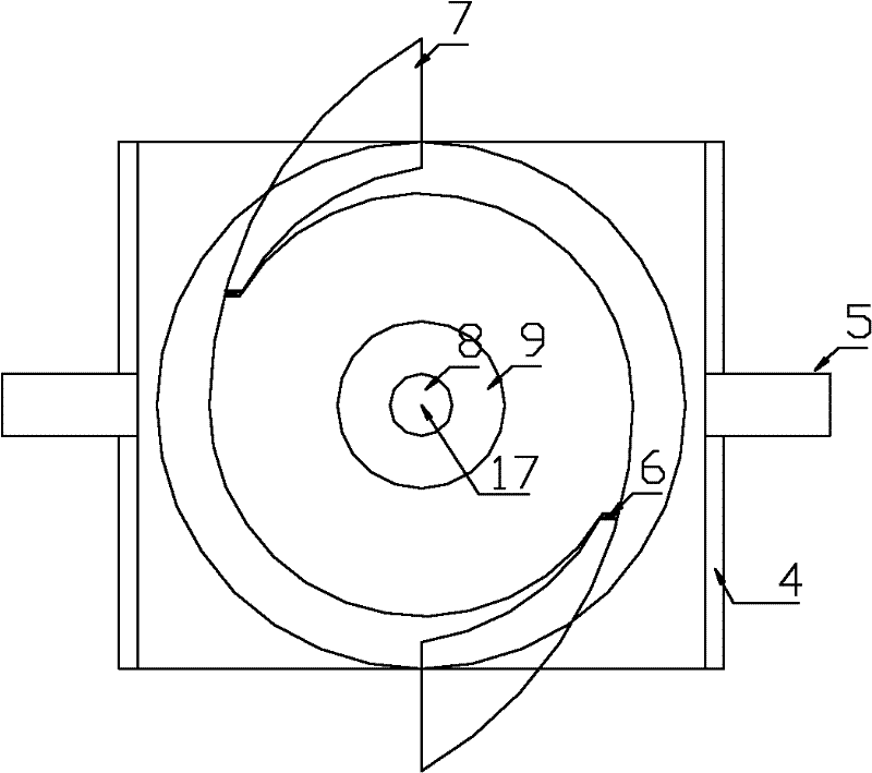
[0049] figure 1 , figure 2 , image 3 Among them, a spin-floating entrainment metallurgical process, which includes gas entry, material entry and gas flow reaction;

[0050] Gas entry: The reaction gas 12 enters the swirl generator 2 tangentially along multiple symmetrical rotary air inlets 7 and is adjusted by the control valve 6 to form a controllable swirling air flow. The wind speed controller 9 controls the outlet area of ​​the swirl generator 2 to control the speed at which the reaction gas enters the reaction furnace 13;

[0051] Material entry: the powdery material flow 11 falls freely around the reaction gas, enters the reaction furnace 13 and is involved in the high-speed rotating air flow;

[0052] Gas flow reaction: the swirling fluid sprayed from top to bottom drives and entrains the furnace gas to form a gas-solid two-phase mixed swir...


PUM


Abstract

The invention relates a floating entrainment metallurgical process. In this process, the reaction gas and the powdery materials are injected into the reaction furnace, aiming to obtain a controllable highly rotating and floating state and reach the ignition point under the high-temperature radiation of the reaction furnace to combust intensely. Meanwhile, the rotating fluid injected in the reaction furnace will drive the furnace gas, and forms a relatively low-temperature circular backflow protection area around the rotating fluid. The reaction gas is tangentially fed into the rotating generator along numbers of rotary channels to form a controllable rotating airflow, in addition, a conical exit air controller that can be moved up and down is adopted to control the exit area of the rotating generator, thus controlling the velocity of the reaction gas into the reaction furnace; the powdery materials fall freely around the reaction gas and are involved in the high-speed rotating airflow, forming a rotating fluid, of which the powdery materials are highly dispersed into the reaction gas, moving downwards along the radial high-speed rotating axle. For the purpose of this invention, a steplessly adjusted reactor is as well referred to in this invention.

Description

technical field [0001] The invention relates to a nonferrous metallurgical process and device, in particular to a spin-floating entrainment metallurgical process and a reactor thereof. Background technique [0002] In the non-ferrous metal industry, pyrometallurgy is a process in which sulfur and iron in sulfide ores are finally removed by reacting with oxygen to obtain non-ferrous metals. With the development of the metallurgical industry, the advancement of science and technology, and the higher and higher environmental protection requirements, strengthening the smelting process and reducing production costs have become important issues in the metallurgical industry, and promote the continuous emergence of new metallurgical processes. Although the chemical reaction mechanism followed by various processes is the same, the process pyrometallurgical process can be roughly divided into two categories: molten pool smelting and space suspension smelting. The most widely used spa...

Claims


Application Information

Patent Timeline
Patent Type & Authority Applications(China)
IPC IPC(8): C22B15/00
CPCC22B5/12C22B15/00F27B17/00C22B15/0047
Inventor 周松林刘卫东
Owner YANGGU XIANGGUANG COPPER
Why Eureka
Try Eureka