Evaporation fuel purge system
A technology for evaporative fuel and purification system, which is applied to the charging system, adding non-fuel substances to fuel, engine components, etc., and can solve problems such as blocking the flow of evaporative fuel
- Summary
- Abstract
- Description
- Claims
- Application Information
AI Technical Summary
Problems solved by technology
Method used
Image
Examples
no. 1 example
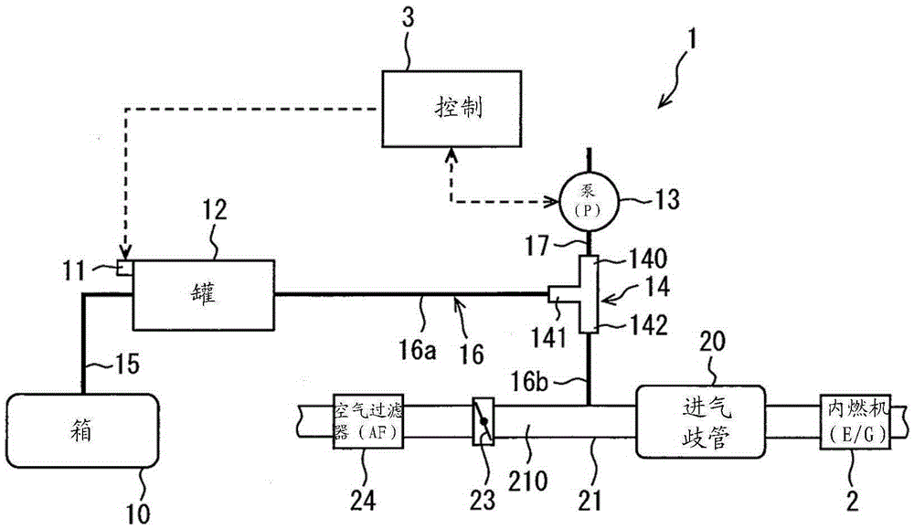
[0024] refer to figure 1 , the evaporated fuel purification system 1 according to the first embodiment will be described. The evaporated fuel purification system 1 supplies, for example, hydrocarbon (HC) gas adsorbed in the fuel in the tank 12 to the intake passage 210 of the internal combustion engine 2 and prevents the evaporated fuel from being discharged into the atmosphere from the fuel tank 10 . like figure 1 As shown, the evaporated fuel purge system 1 is configured with an intake system of the internal combustion engine 2 having an intake passage 210 , and a purge system that supplies evaporated fuel to the intake system of the internal combustion engine 2 .
[0025] The evaporated fuel introduced into the intake passage 210 is mixed with the fuel for combustion supplied from the injector to the internal combustion engine 2 , and burned in the cylinders of the internal combustion engine 2 . The intake system of the internal combustion engine 2 has an intake duct 21 w...
no. 2 example
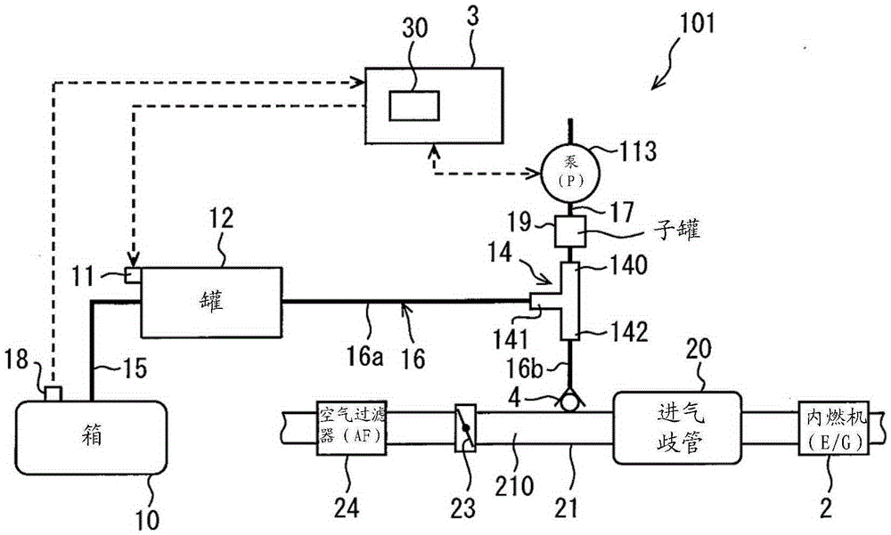
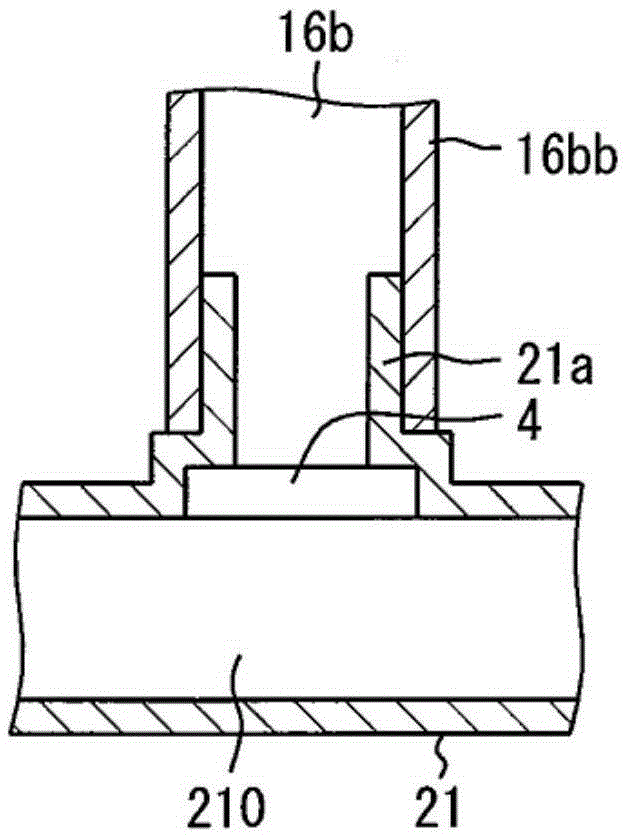
[0046] refer to Figure 2-Figure 6 , the evaporative fuel purification system 101 according to the second embodiment will be described. In the second embodiment, the same composition, operation and effect as those of the first embodiment are not described.
[0047] After the evaporated fuel is generated in the fuel tank 10, the evaporated fuel purification system 101 prevents the evaporated fuel from being discharged into the atmosphere. The concern is that if there is a hole in the purge system, fuel can be vented into the atmosphere as a leak from the evaporative fuel purge system. Furthermore, even if an abnormality such as a leak occurs, it does not exhibit a large influence in the operation of the internal combustion engine 2, so that the driver of the vehicle may not notice the abnormality. Therefore, the object of the second embodiment is to detect abnormalities in the purification system at an early stage.
[0048] The evaporative fuel purification system 101 includ...
no. 3 example
[0080] refer to Figure 8 and Figure 9 , the evaporative fuel purification system 201 according to the third embodiment will be described. In the third embodiment, the same composition, operation, and effect as those of the above embodiment are not described.
[0081] The evaporated fuel purification system 210 includes a concentration detector 5 for detecting the concentration of evaporated fuel in the fuel-air mixture of air and evaporated fuel entering the intake passage 210 after purification. The concentration detector 5 will be described below. The concentration detector 5 includes a differential pressure sensor, a sub-tank, a first solenoid valve, a second solenoid valve, a gas choke, a first detection channel, a second detection channel, and an atmosphere channel.
[0082] One end of the first detection channel is connected to the middle of the purification channel 16 . The other end of the first detection channel is connected to one end of the second detection ch...
PUM
 Abstract
Description
Claims
Application Information
 - R&D
- Intellectual Property
- Life Sciences
- Materials
- Tech Scout
- Unparalleled Data Quality
- Higher Quality Content
- 60% Fewer Hallucinations
Browse by: Latest US Patents, China's latest patents, Technical Efficacy Thesaurus, Application Domain, Technology Topic, Popular Technical Reports.
© 2025 PatSnap. All rights reserved.Legal|Privacy policy|Modern Slavery Act Transparency Statement|Sitemap|About US| Contact US: help@patsnap.com


