Low voltage driven knife-type gate valve body

A knife gate valve, low voltage technology, applied in sliding valves, valve details, valve devices, etc., can solve the problems of large system resistance, limited sealing strength, inability to rotate, etc., to increase system resistance, improve sealing effect, and not easy to rust deformation effect

Inactive Publication Date: 2015-05-27
HEILONGJIANG TIANHAI ENERGY SAVING TECH DEV
View PDF7 Cites 1 Cited by
  • Summary
  • Abstract
  • Description
  • Claims
  • Application Information

AI Technical Summary

Problems solved by technology

Electrothermal valves are prone to actuator failure after long-term use, resulting in valve failure. Normally open electric valves require a stable power supply for continuous power supply, so energy consumption is high; electric valves are divided into electric ball valves and electric gate valves. It is easy to be stuck by foreign matter or the spherical surface of the valve core is deformed due to corrosion and cannot rotate. However, most of the gate opening forms of existing electric gate valves are screw rods directly driving the gate plate to lift, and most of the screw rods are exposed outside the valve body when they are lifted. The electric gate valve with this structure has a limited stroke and it is difficult to fully open, so the system resistance will be relatively large, which will have a certain impact on the heat supply flow. In addition, the screw needs to move up and down, so the sealing strength at the screw is limited, and repeated lifting And the dust attached to the exposed screw will further affect the sealing strength of the screw. In addition, it is necessary to reserve a part of space above the valve during installation for the screw to go up and down.

Method used


Image

  • Low voltage driven knife-type gate valve body
  • Low voltage driven knife-type gate valve body

Examples


Embodiment Construction

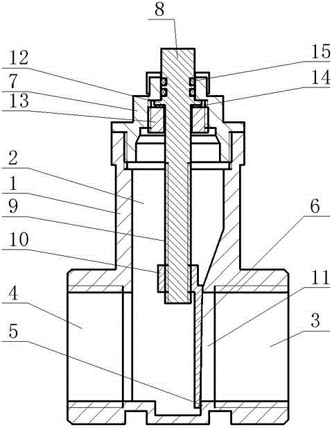
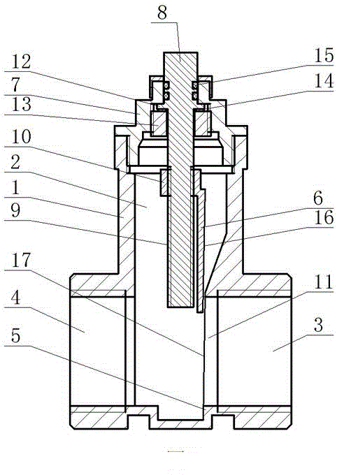
[0008] The low-voltage driven knife-type gate valve body of the present invention includes a valve body 1, a cavity 2 is arranged in the valve body 1, one side of the lower part of the cavity 2 communicates with the pipe joint 3 at the inlet end, and the other side of the lower part of the cavity 2 communicates with the outlet The end pipe joint 4 is connected, and the position where the cavity 2 communicates with the inlet end pipe joint 3 is provided with an annular step 5, and the inside of the annular step 5 forms a water inlet channel 11 communicated with the inlet end pipe joint 3, and the gate 6 is installed in the cavity 2 , the gate 6 is closely matched with the annular step 5, the valve seat 7 is installed on the top of the cavity 2, the valve stem 8 is arranged inside the valve seat 7, the valve stem 8 and the valve seat 7 are sealed by a seal, and the lower part of the valve stem 8 is provided with an external thread 9. The screw sleeve 10 is installed on the extern...


PUM


Abstract

The invention discloses a low voltage driven knife-type gate valve body. The low voltage driven knife-type gate valve body comprises a valve body, wherein a cavity is formed in the valve body; one side of the lower part of the cavity is communicated with a pipe joint at an inlet end; the other side of the lower part of the cavity is communicated with the pipe joint at an outlet end; a position, communicated with the pipe joint at the inlet end, inside the cavity, is provided with an annular step; a gate plate is mounted inside the cavity and forms close fit with the annular step; a valve seat is mounted at the top of the cavity; a valve rod is arranged inside the valve seat; the valve rod and the valve seat are sealed by a sealing part; the lower part of the valve rod is provided with external threads. The low voltage driven knife-type gate valve body disclosed by the invention has the advantages of being long in service life, low in fault rate of an executing mechanism, capable of being maintained in the current state after the power is off and needing no continuous power supply, relatively low in energy consumption, stable in operation, unlikely to block by foreigner materials and unlikely to rust and deform; the gate plate can be completely opened without increasing the resistance of the system and without moving up and down; during installation, no space needs to be preset in the upper direction; meanwhile, the sealing effect of the low voltage driven knife-type gate valve body is effectively improved.

Description

technical field [0001] The invention relates to a room temperature control valve, in particular to a low-voltage driven knife-type gate valve body. Background technique [0002] At present, the room temperature control valves used in the heating metering system are roughly divided into two types: electric valves and electric heating valves. Electrothermal valves are prone to actuator failure after long-term use, resulting in valve failure. Normally open electric valves require a stable power supply for continuous power supply, so energy consumption is high; electric valves are divided into electric ball valves and electric gate valves. It is easy to be stuck by foreign matter or the spherical surface of the valve core is deformed due to corrosion and cannot rotate. However, most of the gate opening forms of existing electric gate valves are screw rods directly driving the gate plate to lift, and most of the screw rods are exposed outside the valve body when they are lifted. ...

Claims


Application Information

Patent Timeline
Patent Type & Authority Applications(China)
IPC IPC(8): F16K3/12F16K41/06
CPCF16K3/0281F16K3/12F16K3/314F16K31/508F16K41/02F16K41/06
Inventor 王建华
Owner HEILONGJIANG TIANHAI ENERGY SAVING TECH DEV
Why Eureka
Try Eureka