Mechanism for reducing quantity of oil accumulated in pump cavity of vacuum pump
A vacuum pump and oil accumulation technology, which is applied to the components, pump components, mechanical equipment, etc. of the pumping device for elastic fluid, which can solve the problem of increasing the starting torque of the vacuum pump, increasing the viscosity of the lubricating oil, and increasing the resistance of the sliding vane. and other problems, to achieve the effect of reducing oil accumulation in the pump cavity, simple structure, and ensuring reliable and stable work.
- Summary
- Abstract
- Description
- Claims
- Application Information
AI Technical Summary
Problems solved by technology
Method used
Image
Examples
Embodiment 1
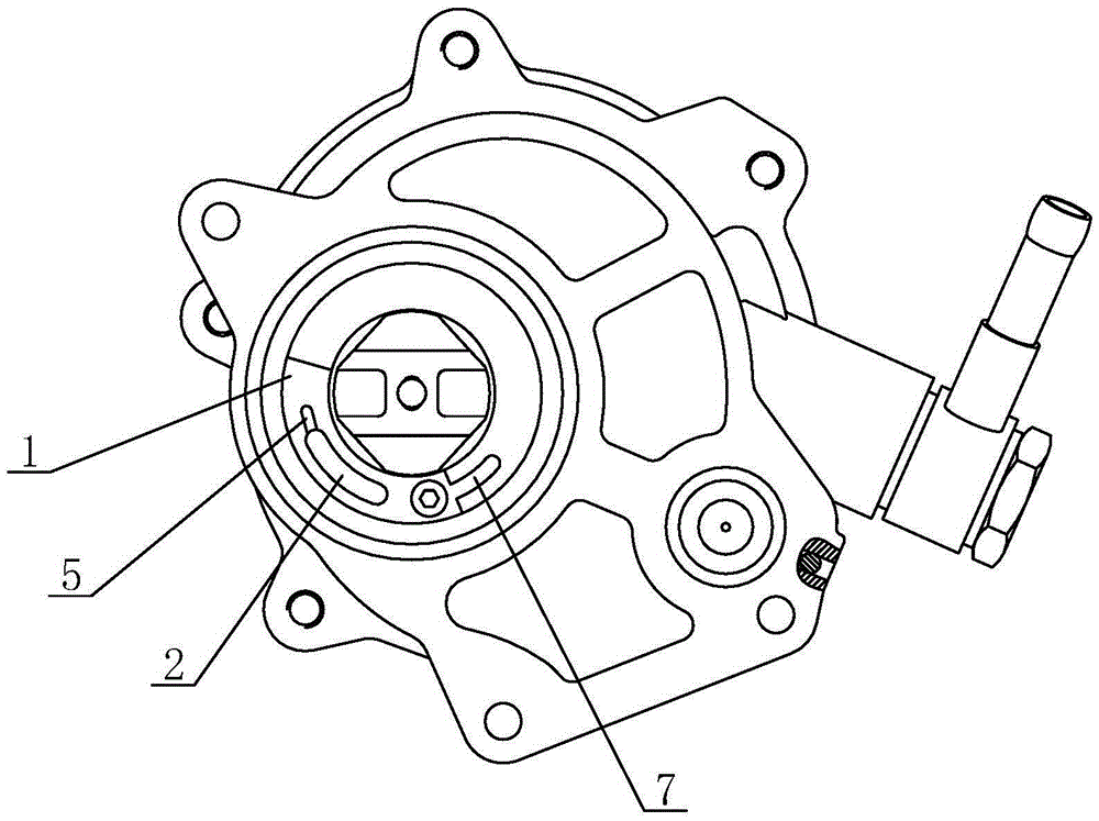
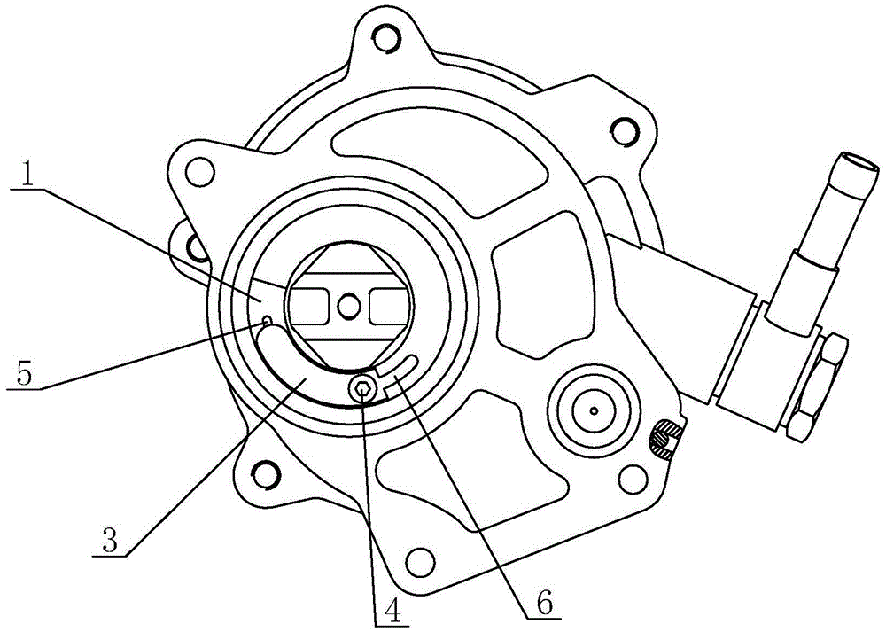
[0021] see figure 1 and figure 2 As shown, in this embodiment, a mechanism for reducing the amount of oil accumulated in the pump chamber of a vacuum pump includes a pump body 1 and an oil discharge hole 2, and the oil discharge hole 2 is opened on the pump body 1 and connected to the pump body The pump cavity is connected, and an oil baffle 3 is arranged on the pump body 1 in conjunction with the oil discharge hole 2. The oil discharge hole 2 is an arc-shaped structure, and the oil baffle 3 cooperates with the oil discharge The hole 2 is also arranged in a circular arc shape, the head end of the oil baffle 3 is fixed on the pump body 1 through the fixing screw 4 as a fixed end, and the tail end is attached to the oil discharge hole 2 as a non-fixed end. At the tail end, the pump body 1 at the tail end of the oil discharge hole 2 is provided with a vent groove 5 with a small section outside the oil baffle plate 3, and the vent groove 5 connects the oil discharge hole 2 with ...
Embodiment 2
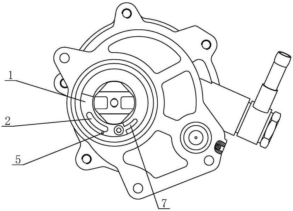
[0024] see image 3 and Figure 4 As shown, the difference between the present embodiment and the first embodiment lies in that the opening positions of the ventilation slots 5 are different, and the other structures are the same. In this embodiment, the oil discharge hole 2 has an arc-shaped structure, and the vent groove 5 is opened on the pump body 1 outside the oil discharge hole 2 and is located at the head end of the oil discharge hole 2 .
Embodiment 3
[0026] see Figure 5 and Image 6 As shown, the difference between the present embodiment and the first embodiment lies in that the opening positions of the ventilation slots 5 are different, and the other structures are the same. In this embodiment, the oil discharge hole 2 has an arc-shaped structure, and the vent groove 5 is opened on the pump body 1 inside the oil discharge hole 2 and is located at the head end of the oil discharge hole 2 .
PUM
 Abstract
Description
Claims
Application Information
 - R&D
- Intellectual Property
- Life Sciences
- Materials
- Tech Scout
- Unparalleled Data Quality
- Higher Quality Content
- 60% Fewer Hallucinations
Browse by: Latest US Patents, China's latest patents, Technical Efficacy Thesaurus, Application Domain, Technology Topic, Popular Technical Reports.
© 2025 PatSnap. All rights reserved.Legal|Privacy policy|Modern Slavery Act Transparency Statement|Sitemap|About US| Contact US: help@patsnap.com


