
Catalytic oxidation heat exchanger and work method thereof

A catalytic oxidation and heat exchanger technology, applied in the direction of indirect heat exchanger, heat exchanger type, catalytic conversion gas purification of impurities, etc., can solve problems such as low power generation efficiency, no major breakthroughs, and potential safety hazards. Achieve the effect of saving resources, realizing heat recovery and utilization, and low cost

Active Publication Date: 2016-04-27
SHANDONG UNIV
View PDF7 Cites 6 Cited by
  • Summary
  • Abstract
  • Description
  • Claims
  • Application Information

AI Technical Summary

Problems solved by technology

[0004] In my country and many countries in the world, the research on low-grade gas utilization technology mainly focuses on: low-grade gas power generation technology, low-grade gas compression technology, low-grade gas combustion technology, and low-grade ga

Method used


Image

  • Catalytic oxidation heat exchanger and work method thereof
  • Catalytic oxidation heat exchanger and work method thereof

Examples


Example Embodiment

[0042] Example 1:

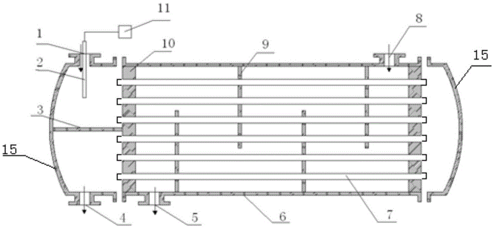
[0043] Such as figure 1 As shown, the catalytic oxidation heat exchanger is used to realize low-grade gas heat recovery and low energy consumption treatment. The heat exchanger can be realized by simple modification of the conventional heat exchanger, and the cost is low. It can adopt the sleeve type and shell and tube plate type. , Spiral plate and other types.

[0044] The catalytic oxidation heat exchanger includes a shell 6, which has heads 15 at both ends of the shell 6 and forms a heat exchange cavity inside; the two ends of the shell 6 are provided with radial tube plates 10 and are sealed; the tube plates 10 are provided for replacement The tube hole through which the heat channel passes. The heat exchange channel connects the two heads 15. One end of the head 15 has a pipe fluid inlet 1 at the top and a pipe fluid outlet 4 at the bottom. The head 15 is divided into two by a horizontal partition 3 In part, the heat exchange channel and the head 15 form ...

Example Embodiment

[0055] Example 2:

[0056] A sealing ring is arranged between the shell 6 and the head 15 for sealing, and a sealing ring is arranged between the heat exchange channel and the radial tube plate 10 for sealing.

Example Embodiment

[0057] Example 3:

[0058] Both the shell 6 and the head 15 are provided with a sealing groove, and an O-ring is fixed in the sealing groove for sealing; the heat exchange channel and the radial tube plate 10 are both provided with a sealing groove, and an O-ring is fixed in the sealing groove for sealing;


PUM


Abstract

The invention discloses a catalytic oxidation heat exchanger and a work method thereof. The catalytic oxidation heat exchanger comprises a shell, a sealing head I and a sealing head II are arranged at the two ends of the shell respectively, and a heat exchange cavity is formed inside the shell; radial tube plates are arranged inside the shell and between the sealing head I and the sealing head II in a sealed mode and are provided with tube holes accepting penetration by heat exchange channels, the sealing head I and the sealing head II are communicated through the heat exchange channels, and the heat exchange channels and the sealing heads form intra-tube fluid channels; a plurality of baffle plates parallel with the radial tube plates are arranged inside the shell and divide the heat exchange cavity for forming exo-tube fluid channels, one ends of the exo-tube fluid channels are communicated with an exo-tube fluid inlet in the top of the shell, and the other ends of the exo-tube fluid channels are communicated with an exo-tube fluid outlet in the bottom of the shell; the heat exchange channels comprise heat exchange tubes, the heat exchange tubes are covered with foam metal, and active particles with the catalytic activity are arranged in the foam metal. According to the invention, the low temperature catalytic oxidation technology is adopted, the problem that low-grade fuel gas is difficult to utilize is solved, and the effects of energy conservation and environmental protection are realized.

Description

technical field [0001] The invention relates to a catalytic oxidation heat exchanger and its working method for realizing low-grade gas heat recovery and low energy consumption treatment. Background technique [0002] Low-grade gas refers to the gas containing low-concentration combustible gas (CH4, CO, H2) that is difficult to use in industrial production. For example, ultra-low concentration coalbed methane, low-quality fossil gas fuels such as mine ventilation, or other low-concentration fuel-type exhaust gases. Under normal conditions, this part of the gas cannot be ignited or sustain combustion. [0003] At present, most of the low-grade combustible gases in the world are directly discharged to the atmosphere without recycling. The emission of such gases, on the one hand, has caused a serious waste of limited non-renewable resources, and on the other hand, has also aggravated environmental pollution and the greenhouse effect. Therefore, reasonable recovery and utiliz...

Claims


Application Information

Patent Timeline
IPC IPC(8): F28D7/16F28F21/08C10K1/34
CPCC10K1/34F28D7/1615F28F21/081F28F2255/00Y02P20/10
Inventor 程星星王志强马春元王鹏李仁
Owner SHANDONG UNIV
Learn More