
Fluid collector

A collector and fluid technology, applied in the field of biomedicine, can solve problems such as low collection efficiency and saliva clogging

Active Publication Date: 2016-04-27
ZHEJIANG SORFA MEDICAL PLASTIC
View PDF15 Cites 2 Cited by
  • Summary
  • Abstract
  • Description
  • Claims
  • Application Information

AI Technical Summary

Problems solved by technology

The invention patent with the publication number CN204708886U also provides a saliva DNA collection bottle, which is convenient for sampling. Although it is equipped with a ventilation structure, it is easy to be blocked by saliva, especially for some viscous samples, it is difficult to enter the bottle , the collection efficiency is relatively low

Method used


Image

  • Fluid collector
  • Fluid collector
  • Fluid collector

Examples


Embodiment 1

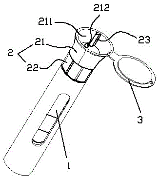
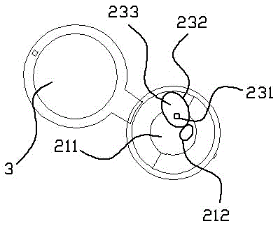
[0020] as attached figure 1 , 2 The fluid collector shown includes a collection bottle 1, a collection body 2 used in conjunction with the collection bottle 1, and a cover 3 hinged on the collection body 2. The collection body 2 includes a collection part 21 and a connecting part 22, The connecting part 22 is screw connected with the bottle mouth of the collecting bottle body 1 , and the collecting part 21 and the connecting part 22 can move back and forth relative to each other in the circumferential direction. The upper surface of the collection part 21 is concave to form a collection surface 211, and the collection surface 211 is provided with a collection hole 212, which cooperates with the matching hole provided on the surface of the connection part 22 to form a fluid channel leading to the collection bottle 1, and collects by rotating Part 21 or connecting part 22, change the relative position of the two, make the collection hole 212 and the matching hole position align...

Embodiment 2

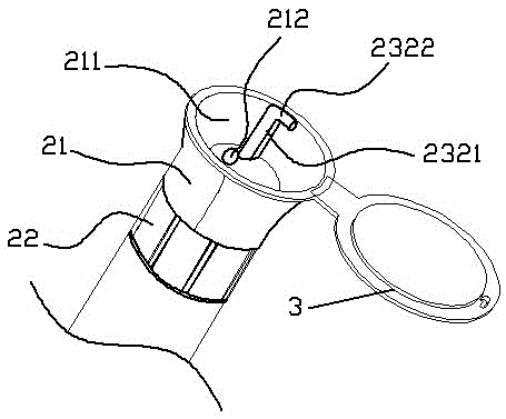
[0022] The difference from Embodiment 1 is that the ventilation wall 232 is arranged on the edge of the collection hole 212, as attached image 3 As shown, it includes a vertical part 2321 and a turning part 2322. The outlet of the ventilation part 23 is arranged at the turning part 2322. The angle between the turning part 2322 and the vertical part 2321 is less than or equal to a right angle. When the included angle is a right angle, the outlet Horizontal, when the included angle is an acute angle, the outlet faces downward, and in this embodiment it is at a right angle, and the outlet of the ventilation part 23 faces the horizontal direction.

Embodiment 3

[0024] The difference from Embodiment 1 is that the ventilation wall 232 includes a vertical portion 2321 and a turning portion 2322 , and a flow guide 2323 aligned with the collection hole 212 extends from the ventilation wall 232 .


PUM


Abstract

The invention relates to a fluid collector, which comprises a collecting bottle body, a collecting body and a cover body, wherein the collecting body is matched with the collecting bottle body to be used; the cover body is hinged onto the collecting body; the collecting body comprises a collecting part and a connecting part; the upper surface of the collecting part is inwards recessed for forming a collecting surface; a collecting hole is formed in the collecting surface; the collecting hole is matched with a matching hole formed in the surface of the connecting part to form a fluid passage communicated to the inside of the collecting bottle body; the collecting part is provided with a ventilation part; an outlet of the ventilation part is higher than the collecting surface; the collecting part is provided with a ventilation auxiliary hole for communicating the bottle body and the ventilation part; the collecting part and the connecting part can relatively move in the circumferential direction. The fluid collector has the advantages that the fluid collection can be performed by the recessed collecting surface of the collecting part; the balance of air pressure inside the bottle and at the outside can be ensured by the ventilation part isolated from the collecting part; the fluid, particularly thick fluid is enabled to smoothly enter the bottle body; an outlet of the ventilation part is arranged in a way of avoiding the direction rightly aligned with the collecting direction; the fluid can be effectively prevented from entering the ventilation part; the ventilation effect is effectively ensured.

Description

technical field [0001] The invention belongs to the technical field of biomedicine and relates to a fluid collector. Background technique [0002] The diagnosis and treatment of many diseases need to be carried out with the help of some samples in the patient's body, such as tests using saliva, urine, blood, etc. The sampling of these samples requires the help of a special sampling device, such as a saliva collection dropper plus combination device disclosed by the patent number CN203941030; a urine collection tube suitable for clinical testing disclosed by the patent number CN201404233. The invention patent with the publication number CN204708886U also provides a saliva DNA collection bottle, which is convenient for sampling. Although it is equipped with a ventilation structure, it is easy to be blocked by saliva, especially for some viscous samples, it is difficult to enter the bottle , the collection efficiency is relatively low. Contents of the invention [0003] The...

Claims


Application Information

Patent Timeline
Patent Type & Authority Applications(China)
IPC IPC(8): G01N1/10
CPCG01N1/10
Inventor 蒋峥嵘谢小良孙晓晓蒋险峰董国华陈鲲陆丽芳
Owner ZHEJIANG SORFA MEDICAL PLASTIC
Learn More