
A device for testing a stress state of an e-shaped elastic strip of a railroad fastener

A stress state, railway fastener technology, applied in the direction of applying stable tension/pressure to test the strength of materials, can solve the problems of insufficient fastener pressure, difficult on-site testing, e-shaped elastic strip breakage, etc. The method is simple and economical The effect of detection time

Inactive Publication Date: 2016-04-27
BEIJING JIAOTONG UNIV +1
View PDF7 Cites 5 Cited by
  • Summary
  • Abstract
  • Description
  • Claims
  • Application Information

AI Technical Summary

Problems solved by technology

However, it also exposed the problems of insufficient buckle pressure and large dispersion during its use, especially in some areas where a large number of e-shaped clips even broke, which posed a great threat to the operation of the train, so it is necessary to test it
[0003] The traditional method of testing the pressure of the e-clip buckle is to use a hydraulic universal servo testing machine for loading experiments, which must be carried out in a large laboratory, and it is difficult to conduct on-site testing in practice
Furthermore, traditional methods cannot be used to carry out buckle pressure tests on the e-type clips at the railway site, let alone test the stress state of the e-type clips, so that it is impossible to find the cause of the damage and fracture of the e-type clips, and it is impossible to Accurate evaluation of the force state of the e-clip

Method used


Image

  • A device for testing a stress state of an e-shaped elastic strip of a railroad fastener
  • A device for testing a stress state of an e-shaped elastic strip of a railroad fastener
  • A device for testing a stress state of an e-shaped elastic strip of a railroad fastener

Examples


Embodiment Construction

[0022] The specific implementation manner of the present invention will be described below in conjunction with the accompanying drawings.

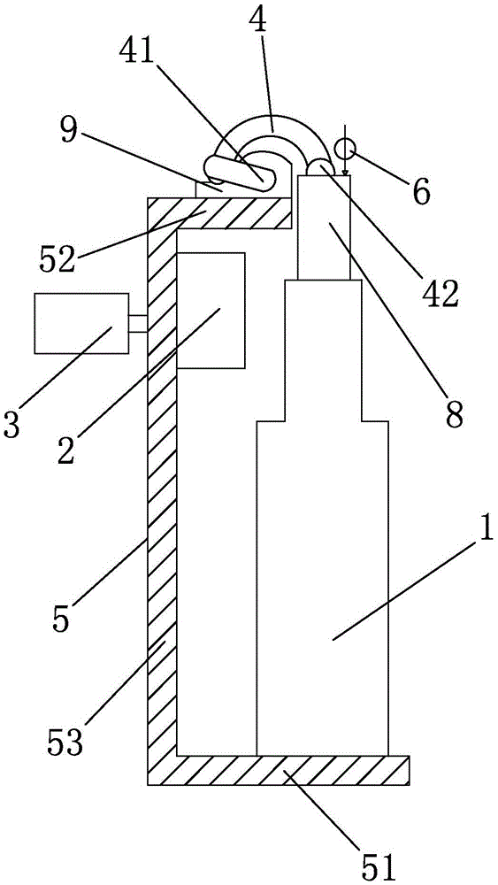
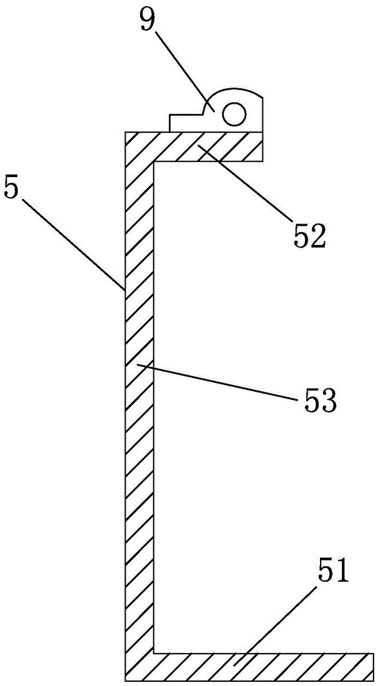
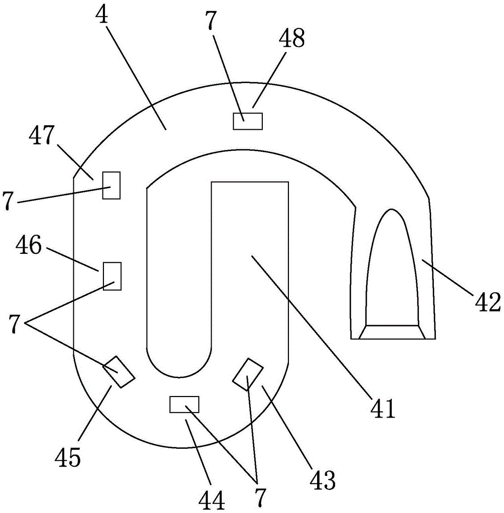
[0023] Such as figure 1 , 2 , shown in 3, a kind of device that is used for the test of the stressed state of railway fastener e-type elastic strip, described device comprises jack 1, data acquisition processor 2, data display screen 3, is used for and the e-type elastic strip to be tested 4 The middle limb 41 is fixedly assembled together with the force bearing bracket 5, the electronic displacement gauge 6 for measuring the vertical displacement of the toe end 42 of the e-shaped elastic strip 4 to be tested and the strain sensor attached to the upper surface of the e-shaped elastic strip 4 to be tested 7; the end of the ejector rod of the jack 1 is provided with a load cell 8 for propping up on the bottom surface of the toe end 42 of the e-shaped elastic bar to be tested; the measuring head of the electronic displacement meter 6 is loca...


PUM


Abstract

A device for testing a stress state of an e-shaped elastic strip of a railroad fastener is disclosed. The device comprises a jack, a data collecting processor, a data displaying screen, a stress holder with which a middle leg of an e-shaped elastic strip to be tested are assembled, an electronic displacement meter used for measuring a vertical displacement of a toe end of the e-shaped elastic strip to be tested and a strain transducer adhered to the surface of the e-shaped elastic strip to be tested. The data collecting processor and the data displaying screen are separately fixed to the stress holder. The jack is disposed at a bottom plate of the stress holder. The top of an ejector rod of the jack is provided with a force transducer propped against the bottom surface of the toe end of the e-shaped elastic strip to be tested. The device can effectively and rapidly test the stress state of the e-shaped elastic strip on site, a testing result is further compared with theoretical analysis results and standards, and the stress state of the e-shaped elastic strip can be evaluated.

Description

technical field [0001] The invention relates to a force testing device, in particular to a device for testing the force state of e-shaped spring bars of railway fasteners. Background technique [0002] The e-type clip is widely used in railways and urban rail transit. It has the advantages of fewer parts, eliminating the need for re-tightening and oiling of traditional fastener bolts, and greatly reducing the maintenance and repair workload. However, it also exposed the problems of insufficient buckle pressure and large dispersion during its use, especially in some areas where a large number of e-shaped clips even broke, which posed a great threat to the operation of the train, so it is necessary to Test it out. [0003] The traditional method of testing the pressure of the e-clip buckle is to use a hydraulic universal servo testing machine for loading experiments, which must be carried out in a large laboratory, and it is difficult to carry out on-site testing in practice....

Claims


Application Information

Patent Timeline
Patent Type & Authority Applications(China)
IPC IPC(8): G01N3/10
CPCG01N3/10
Inventor 肖宏高亮辛涛张艳荣王嘉斌冷雪莹何洋霍磊令行陆永港
Owner BEIJING JIAOTONG UNIV
Learn More