Main bearing member for optical minimal satellite and common structure of optical camera

An optical camera and micro-satellite technology, applied in the field of space optical remote sensing, can solve the problems of high functional density, good rigidity, and small size of lightweight micro-optical satellites

Inactive Publication Date: 2016-04-27
CHANGGUANG SATELLITE TECH CO LTD
View PDF4 Cites 1 Cited by
  • Summary
  • Abstract
  • Description
  • Claims
  • Application Information

AI Technical Summary

Problems solved by technology

The disadvantage of this structure is that it needs 10 structural plates to be spliced ​​together, which requires high processing precision; The camera hood is shared, which

Method used


Image

  • Main bearing member for optical minimal satellite and common structure of optical camera
  • Main bearing member for optical minimal satellite and common structure of optical camera

Examples


Embodiment Construction

[0017] The present invention will be described in detail below in conjunction with the accompanying drawings.

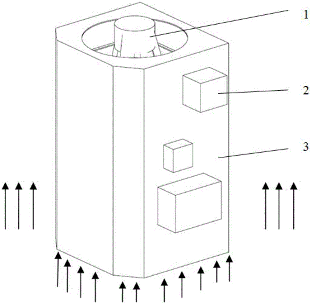
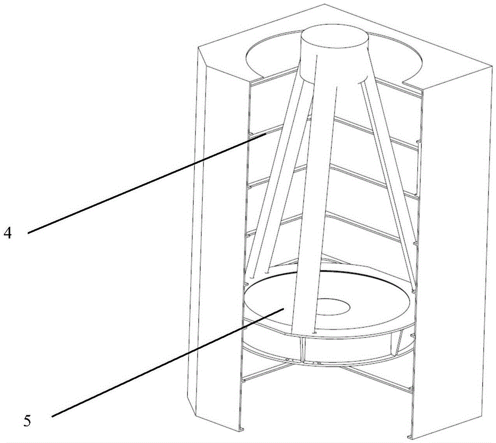
[0018] The technical scheme of the present invention is as figure 1 , figure 2 shown. A co-structure for the main load-bearing component of an optical microsatellite and an optical camera, comprising: an optical camera 1 , a stand-alone camera 2 , a carbon fiber co-structure 3 , an aperture 4 , and a main reflector 5 . The carbon fiber co-structure 3 plays the role of the camera hood and the main load-bearing structure at the same time. The aperture 4 eliminates stray light for the main mirror 5 of the optical camera 1. The on-star stand-alone 2 is installed on the carbon fiber co-structure 3 .

[0019] Explanation of working principle: On the one hand, for an optical camera, the carbon fiber co-structure 3 is the lens hood of the camera, and the main function of the diaphragm 4 is to eliminate stray light for the main mirror 5 of the optical camera 1 . On the ot...


PUM


Abstract

The invention relates to a main bearing member used for optical minimal satellite and a common structure of an optical camera. The main bearing member comprises an optical camera, an on-satellite standalone device, a carbon fiber common structure, a diaphragm and a main reflector; the diaphragm can eliminate the stray light of a main reflector of the optical camera; and the on-satellite standalone device is installed on the fiber common structure. The invention provides a common structure for the main bearing structure of the optical small satellite and provides a common structure of the optical camera, both the main bearing structure and the common structure have functions of the camera light shielding housing and the satellite main bearing, improves the function utilization rate of the on-satellite structure member, and thus improves the space utilization rate in order to reduce the enveloping size and reduce the weight of the integral satellite.

Description

technical field [0001] The invention belongs to the technical field of space optical remote sensing, and in particular relates to a common structure for the main load-bearing component and optical camera of an optical microsatellite. Background technique [0002] Microsatellites are often launched in the form of one rocket with multiple satellites or carrying them. In this case, the carrying weight and space size that the launch vehicle can provide are extremely limited. Therefore, it is necessary to strictly control the envelope size and weight of the microsatellites. The structural design of satellites presents demanding requirements. For optical remote sensing satellites, the whole star optical camera generally occupies a large space, and the space utilization rate of the traditional whole star structure with optical load plus main load-bearing structure is usually low, which is not suitable for the structural design of microsatellites. Therefore, designing a satellite s...

Claims


Application Information

Patent Timeline
IPC IPC(8): G02B7/00G02B7/183
CPCG02B7/00G02B7/183
Inventor 王栋谭陆洋李林
Owner CHANGGUANG SATELLITE TECH CO LTD
Why Eureka
Try Eureka